|
| Place of Origin: | Japan |
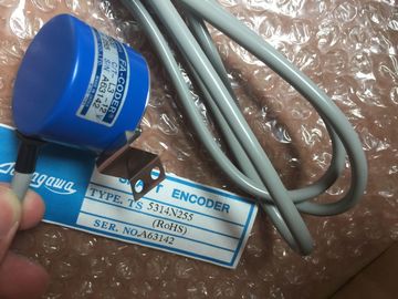
| Brand Name: | Tamagawa |
| Certification: | CE |
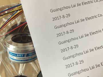
| Model Number: | TS2650N11E78 |
| Minimum Order Quantity: | 1pcs |
|---|---|
| Packaging Details: | carton |
| Delivery Time: | in stock |
| Payment Terms: | T/T, Western Union, MoneyGram |
| Supply Ability: | 100pcs/week |
| TAMAGAWA: | TAMAGAWA | TS2650N11E78: | TS2650N11E78 |
|---|---|---|---|
| Japan: | Japan | Material: | Iron |
| Color: | Black | Wire: | Wire |
| Temperature: | 30-90 | Dimension: | 40mm |
| Pulse and direction outputs | The maximum pulse frequency of the pulse output generators is 100 KHz for the digital outputs of the CPU |
| Power section for stepper motor | 20 KHz for the digital outputs of the standard SB, and 200 KHz for the digital outputs of the high-speed SBs (or 100 KHz for MC V1 instructions). |
| Power section for servo motor | The DC/DC/DC variants of the CPU have onboard |
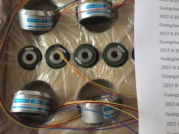
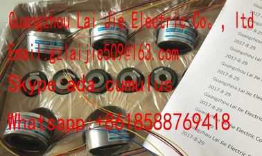
Guang Zhou Lai Jie Electric Co.,LTD
TS5246N160
TS3653N14E12
TS3653N58E5
TS3653N65E27
TS3653N81E27
TS3653N78E5
TS3653N94E5
TS3653N181E8
TS3658N3
TS3664N1E1
TS3664N1E2
TS3664N2E3
TS3664N2E4
TS3664N50
TS3664N50
TS3667N1E2
TS3667N11E2
TS3667N2E5
TS3667N2E6
TS3667N3E7
outputs for direct control of drives. The relay variants of the
CPU require the signal board with DC outputs for drive
control.
A signal board (SB) expands the onboard I/O to include a few additional I/O points. An SB
with 2 digital outputs can be used as pulse and direction outputs to control one motor. An SB
with 4 digital outputs can be used as pulse and direction outputs to control two motors. Builtin
relay outputs cannot be used as pulse outputs to control motors.
Note
Pulse-train outputs cannot be used by other instructions in the user program
When you configure the outputs of the CPU or signal board as pulse generators (for use with
the PWM or motion control instructions), the corresponding output addresses (Q0.0 to Q0.3,
Q4.0 to Q4.3) are removed from the Q memory and cannot be used for other purposes in
your user program. If your user program writes a value to an output used as a pulse
generator, the CPU does not write that value to the physical output.
Table 9- 22 Maximum number of controllable drives
Type of CPU No SB installed With an SB
(2 x DC outp
In the Project tree, expand the node "Technological Objects" and select "Add new
object".
– Select the "Axis" icon (rename if required) and click "OK" to open the configuration
editor for the axis object.
– Display the "Select PTO for Axis Control" properties under the "Basic parameters" and
select the desired pulse. Note the two Q outputs assigned for pulse and direction.
Note
If the PTO has not been previously configured in the CPU Properties, the PTO is
configured to use one of the onboard outputs.
If you use an output signal board, then select the "Device configuration" button to go
to the CPU Properties. Under "Parameter assignment", in the "Pulse options",
configure the output source to a signal board output. "Pulse_1" and "Pulse_3"are the
only pulse outputs available on the signal board.
– Configure the remaining Basic and Extended parameters.
2. Program your application: Insert the MC_Power instruction in a code block.
– For the Axis input, select the axis technology object that you created and configured.
– Setting the Enable input to TRUE allows the other motion instructions to function.
– Setting the Enable input FALSE cancels the other motion instructions.
Note
Include only one MC_Power instruction per axis.
. Insert the other motion instructions to produce the required motion.
Note
Configuring a pulse generator to signal board outputs: Select the "Pulse generators
(PTO/PWM)" properties for a CPU (in Device configuration) and enable a pulse generator.
Two pulse generators are available for each CPU V1.0, V2.0, V2.1, and V2.2.
CPU V3.0 CPUs have four pulse generators available. In this same configuration
area under "Pulse options", select Pulse generator used as: "PTO".