|
| Place of Origin: | Japan |
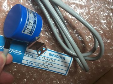
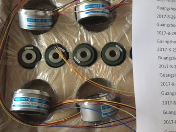
| Brand Name: | Tamagawa |
| Certification: | CE |
| Model Number: | TS2651N1E78 |
| Minimum Order Quantity: | 1pcs |
|---|---|
| Packaging Details: | carton |
| Delivery Time: | in stock |
| Payment Terms: | T/T, Western Union, MoneyGram |
| Supply Ability: | 100pcs/week |
| TAMAGAWA: | TAMAGAWA | Material: | Iron |
|---|---|---|---|
| Color: | Black | TS2651N1E78: | TS2651N1E78 |
| Temperature: | 20-80 | Wire: | Wire |
| Dimension: | 50mm | Japan: | Japan |
| If you have downloaded multiple firmware updates to the memory card for multiple modules, | |
| the CPU applies the updates in the order in which you downloaded them to the memory card. Recovery from a lost password |
|
| If you have lost the password for a password-protected CPU, use an empty transfer card to |
Guang Zhou Lai Jie Electric Co.,LTD
TS2651N1E78
TS3617N2E4
TS3630N11E1
TS3664N2E4
TS3653N13E7
TS3653N12E6
TS3653N2E5
TS3624N2E3
TS3653N13E9
TS3653N2E6
TS3653N3E7
TS3653N3E8
TS3653N3E9
TS1980N43E12
TS1980N56E12
TS1981N134E9
TS1981N53E19
TS1981N56E19
TS1981N56E19
TS1982N126E6
TS1982N128E6
TS1982N53E6
TS1982N56E18
TS1983N146E5
TS252N30E1
TS3503N11E43
delete the password-protected program. The empty transfer card erases the internal load
memory of the CPU. You can then download a new user program from STEP 7 to the CPU.
For information about the creation and use of an empty transfer card, see the section of
transfer cards (Page 110).
WARNING
If you insert a transfer card in a running CPU, the CPU goes to STOP. Control devices can
fail in an unsafe condition, resulting in unexpected operation of controlled equipment. Such
unexpected operations could result in death or serious injury to personnel, and/or damage
to equipment.
You must remove the transfer card before setting the CPU to RUN mode.Communication module (CM) or communication processor (CP): Up to 3, inserted in slots 101,
102, and 103
② CPU: Slot 1
③ Ethernet port of CPU
④ Signal board (SB), communication board (CB) or battery board (BB): up to 1, inserted in the
CPU
⑤ Signal module (SM) for digital or analog I/O: up to 8, inserted in slots 2 through 9
(CPU 1214C and CPU 1215C allow 8, CPU 1212C allows 2, CPU 1211C does not allow any)
To create the device configuration,
add a device to your project.
In the Portal view, select
"Devices & Networks" and click
"Add new device".
In the Project view, under the
project name, double-click "Add
new device". You create your device configuration by inserting a CPU into your project. Be sure you insert
the correct model and firmware version from the list. Selecting the CPU from the "Add new
device" dialog creates the rack and CPU.
"Add new device" dialog Selecting the CPU in the Device
view displays the CPU
properties in the inspector
window. The CPU does not have a pre-configured IP address. You must manually assign an IP
address for the CPU during the device configuration. If your CPU is connected to a router on
the network, you also enter the IP address for a router. If you are connected to a CPU, you can upload the
configuration of that CPU, including any modules, to your
project. Simply create a new project and select the "unspecified
CPU" instead of selecting a specific CPU. (You can also skip
the device configuration entirely by selecting the "Create a PLC
program" from the "First steps". STEP 7 then automatically
creates an unspecified CPU.)
From the program editor, you select the "Hardware detection"
command from the "Online" menu.
From the device configuration editor, you select the option for detecting the configuration of
the connected device. After you select the CPU from the online dialog and click the Load button, STEP 7 uploads
the hardware configuration from the CPU, including any modules (SM, SB, or CM). You can
then configure the parameters for the CPU and the modules. Use the hardware catalog to add modules to the CPU:
● Signal module (SM) provides additional digital or analog I/O points. These modules are
connected to the right side of the CPU.
TS3062E3