 |
| Place of Origin: | Japan |
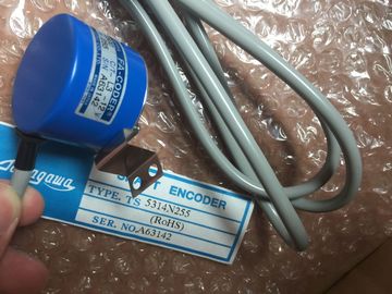
| Brand Name: | Tamagawa |
| Certification: | CE |
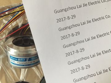
| Model Number: | TS2651N131E78 |
| Minimum Order Quantity: | 1pcs |
|---|---|
| Packaging Details: | carton |
| Delivery Time: | in stock |
| Payment Terms: | T/T, Western Union, MoneyGram |
| Supply Ability: | 100pcs/week |
| TAMAGAWA: | TAMAGAWA | TS2651N131E78: | TS2651N131E78 |
|---|---|---|---|
| Material: | Iron | Color: | Black |
| Japan: | Japan | Temperature: | 20-80 |
| Wire: | Wire | Dimension: | 80mm |
| Signal board (SB) provides just a few additional I/O points for the CPU. The SB is | |
| installed on the front of the CPU. | |
| Battery Board 1297 (BB) provides long-term backup of the realtime clock. The BB is instal |
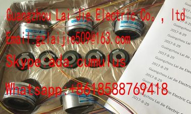
Guang Zhou Lai Jie Electric Co.,LTD
TS2651N131E78
TS1982N56E18
TS1983N146E5
TS252N30E1
TS3503N11E43
TS3062E3
Communication board (CB) provides an additional communication port (such as RS485).
The CB is installed on the front of the CPU.
● Communication module (CM) and communication processor (CP) provide an additional
communication port, such as for PROFIBUS or GPRS. These modules are connected to
the left side of the CPU.
To insert a module into the device configuration, select the module in the hardware catalog
and either double-click or drag the module to the highlighted slot. You must add the modules
to the device configuration and download the hardware configuration to the CPU for the
modules to be functional.
Table 5- 1 Adding a module to the device configuration To configure the operational parameters for the CPU, select the CPU in the Device view
(blue outline around whole CPU), and use the "Properties" tab of the inspector window.
To configure input filter times, select "Digital
Inputs". The default filter time for the digital
inputs is 6.4 ms.
Each input point has a single filter
configuration that applies to all uses: process
inputs, interrupts, pulse catch, and HSC
inputs. If an HSC is not configured to use a point, the filter setting chosen in this screen applies. If
an HSC is configured to use an input point, the filter setting for that point is automatically set
at 800 ns and is not affected by the configuration on this screen.
WARNING
If the filter time for a digital input channel is changed from a previous setting, a new "0"
level input value may need to be presented for up to 20.0 ms accumulated duration before
the filter becomes fully responsive to new inputs. During this time, short "0" pulse events of
duration less than 20.0 ms may not be detected or counted.
This changing of filter times can result in unexpected machine or process operation, which
may cause death or serious injury to personnel, and/or damage to equipment.
To ensure that a new filter time goes immediately into effect, a power cycle of the CPU
must be applied. PROFINET interface Sets the IP address for the CPU and time synchronization
DI, DO, and AI Configures the behavior of the local (on-board) digital and analog I/O (for example, digital
input filter times and digital output reaction to a CPU stop).
High-speed counters
(Page 337) and pulse
generators (Page 311)
Enables and configures the high-speed counters (HSC) and the pulse generators used for
pulse-train operations (PTO) and pulse-width modulation (PWM)
When you configure the outputs of the CPU or signal board as pulse generators (for use with
the PWM or motion control instructions), the corresponding output addresses (Q0.0, Q0.1,
Q4.0, and Q4.1) are removed from the Q memory and cannot be used for other purposes in
your user program. If your user program writes a value to an output used as a pulse
generator, the CPU does not write that value to the physical output.Startup after POWER ON: Selects the behavior of the CPU following an off-to-on transition,
such as to start in STOP mode or to go to RUN mode after a warm restart
Supported hardware compatibility: Configures the substitution strategy for all system
components (SM, SB, CM, CP and CPU):
Allow acceptable substitute
Allow any substitute (default)
Each module internally contains substitution compatibility requirements based on the
number of I/O, electrical compatibility, and other corresponding points of comparison. For
example, a 16-channel SM could be an acceptable substitute for an 8-channel SM, but an 8-
channel SM could not be an acceptable substitute for a 16-channel SM. If you select "Allow