|
| Place of Origin: | Japan |
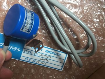
| Brand Name: | Tamagawa |
| Certification: | CE |
| Model Number: | TS5013N61 |
| Minimum Order Quantity: | 1pcs |
|---|---|
| Packaging Details: | carton |
| Delivery Time: | in stock |
| Payment Terms: | T/T, Western Union, MoneyGram |
| Supply Ability: | 100pcs/week |
| TAMAGAWA: | TAMAGAWA | TS5013N61: | TS5013N61 |
|---|---|---|---|
| Japan: | Japan | Material: | Iron |
| Color: | Black | Temperature: | 40-80 |
| Dimension: | 50mm | Wire: | Wire |
Each station (or IO device) starts up independently on start-up,
| Each station (or IO device) starts up independently on start-up, | If this situation occurs, false station errors will result. |
| and this affects the overall CPU start-up time |
In the CPU Properties under "Startup", you can find the "Parameter assignment time for |
| If you set the configurable time-out too low, there may not be a sufficient overall CPU start-up time for all stations to complete start-up. |
distributed I/O" (time-out). |
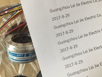
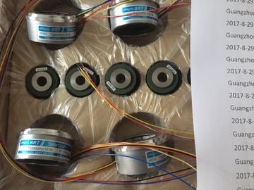
Guang Zhou Lai Jie Electric Co.,LTD
TS5013N61
TS5210N54
TS5210N553
TS3684N1E3
TS3684N2E6
TS3684N3E8
TS3684N11E3
TS3684N12E6
TS3684N13E8
TS3617N1E3
TS3617N1E1
TS3617N1E2
TS3617N2E4
TS3617N2E5
TS3617N2E6
TS3617N2E7
TS3617N3E8
TS3617N3E9
TS3617N3E1
TS3617N11E3
TS3617N11E1
TS3617N11E2
TS3617N12E4
TS3617N12E5
The default configurable time-out is 60,000 ms (1 minute); the
user can configure this time. All PROFINET devices must have a Device Name and an IP Address. Use STEP 7 to define
the Device Names and to configure the IP addresses. Device names are downloaded to the
IO devices using PROFINET DCP (Discovery and Configuration Protocol).The controller broadcasts the names of the devices to the network, and the devices respond
with their MAC addresses. The controller then assigns an IP address to the device using
PROFINET DCP protocol:
● If the MAC address has a configured IP address, then the station performs start-up.
● If the MAC address does not have a configured IP address, STEP 7 assigns the address
that is configured in the project, and the station then performs start-up.
● If there is a problem with this process, a station error occurs and no start-up takes place.
This situation causes the configurable time-out value to be exceeded. When designing a PLC system, you can choose from a variety of methods and criteria. The
following general guidelines can apply to many design projects. Of course, you must follow
the directives of your own company's procedures and the accepted practices of your own
training and location.
Partition your process
or machine
Divide your process or machine into sections that have a level of independence from each other.
These partitions determine the boundaries between controllers and influence the functional
description specifications and the assignment of resources.
Create the functional
specifications
Write the descriptions of operation for each section of the process or machine, such as the I/O
points, the functional description of the operation, the states that must be achieved before
allowing action for each actuator (such as a solenoid, a motor, or a drive), a description of the
operator interface, and any interfaces with other sections of the process or machine.
Design the safety
circuits
Identify any equipment that might require hard-wired logic for safety. Remember that control
devices can fail in an unsafe manner, which can produce unexpected startup or change in the
operation of machinery. Where unexpected or incorrect operation of the machinery could result in
physical injury to people or significant property damage, consider the implementation of
electromechanical overrides (which operate independently of the PLC) to prevent unsafe
operations. The following tasks should be included in the design of safety circuits:
? Identify any improper or unexpected operation of actuators that could be hazardous.
? Identify the conditions that would assure the operation is not hazardous, and determine how
to detect these conditions independently of the PLC.
? Identify how the PLC affects the process when power is applied and removed, and also
identify how and when errors are detected. Use this information only for designing the normal
and expected abnormal operation. You should not rely on this "best case" scenario for safety
purposes.
? Design the manual or electromechanical safety overrides that block the hazardous operation
independent of the PLC.
? Provide the appropriate status information from the independent circuits to the PLC so that
the program and any operator interfaces have necessary information.
? Identify any other safety-related requirements for safe operation of the process.
Plan system security Determine what level of protection (Page 164) you require for access to your process. You can
password-protect CPUs and program blocks from unauthorized access. Specify the operator
stations
Based on the requirements of the functional specifications, create the following drawings of the
operator stations:
? Overview drawing that shows the location of each operator station in relation to the process
or machine.
? Mechanical layout drawing of the devices for the operator station, such as display, switches,
and lights.
? Electrical drawings with the associated I/O of the PLC and signal modules.
Create the
configuration drawings
Based on the requirements of the functional specification, create configuration drawings of the
control equipment:
? Overview drawing that shows the location of each PLC in relation to the process or machine.
? Mechanical layout drawing of each PLC and any I/O modules, including any cabinets and
other equipment.
? Electrical drawings for each PLC and any I/O modules, including the device model numbers,
communications addresses, and I/O addresses.
Create a list of
symbolic names
Create a list of symbolic names for the absolute addresses. Include not only the physical I/O
signals, but also the other elements (such as tag names) to be used in your program.
6.2 Structuring your user program