|
| Place of Origin: | Japan |
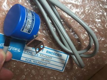
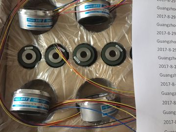
| Brand Name: | Tamagawa |
| Certification: | CE |
| Model Number: | TS5208N131 |
| Minimum Order Quantity: | 1pcs |
|---|---|
| Packaging Details: | carton |
| Delivery Time: | in stock |
| Payment Terms: | T/T, Western Union, MoneyGram |
| Supply Ability: | 100pcs/week |
| Tamagawa: | Tamagawa | TS5208N131: | TS5208N131 |
|---|---|---|---|
| Japan: | Japan | Material: | Iron |
| Temperature: | 30-80 | Color: | Black |
| Any blocks marked in red must be recompiled. | you can use SCL for Boolean logic. Normally open and normally closed contacts |
| LAD and FBD are very effective for handling Boolean logic. While SCL is especially effective | You can connect contacts to other contacts and create your own combination logic. |
| for complex mathematical computation and for project control structures, | If the input bit you specify uses memory identifier I (input) or Q (output), |
Guang Zhou Lai Jie Electric Co.,LTD
TS5208N131
2000144
TS3653N2E4
TS5778N155
TS3624N2E4
TS4559N3E15
TS2151N11E45
TS3738N1E7
TS1980N43E12
482048P6L65V
TS3653N2E5
TS5778N157
TS3624N3E5
TS4886N9079E411
TS2640N321E64
TS3738N1E7
TS1980N56E12
60798024
then the bit
value is read from the process-image register. The physical contact
signals in your control process are wired to I terminals on the PLC. The
CPU scans the wired input signals and continuously updates the
corresponding state values in the process-image input register.
You can specify an immediate read of a physical input using ":P"
following the I offset (example: "%I3.4:P"). For an immediate read, the bit
data values are read directly from the physical input instead of the
process image. An immediate read does not update the process imagThe Normally Open contact is closed (ON) when the assigned bit value is equal to 1.
● The Normally Closed contact is closed (ON) when the assigned bit value is equal to 0.
● Contacts connected in series create AND logic networks.
● Contacts connected in parallel create OR logic networks. In FBD programming, LAD contact networks are transformed into AND (&), OR (>=1), and
exclusive OR (x) box networks where you can specify bit values for the box inputs and
outputs. You may also connect to other logic boxes and create your own logic combinations.
After the box is placed in your network, you can drag the "Insert input" tool from the
"Favorites" toolbar or instruction tree and then drop it onto the input side of the box to add
more inputs. You can also right-click on the box input connector and select "Insert input".
Box inputs and outputs can be connected to another logic box, or you can enter a bit
address or bit symbol name for an unconnected input. When the box instruction is executed,
the current input states are applied to the binary box logic and, if true, the box output will be
trueFor FBD programming, you can drag the "Negate binary input" tool
from the "Favorites" toolbar or instruction tree and then drop it on an
input or output to create a logic inverter on that box connector.
The LAD NOT contact inverts the logical state of power flow input.
If there is no power flow into the NOT contact, then there is power
flow out.
If there is power flow into the NOT contact, then there is no power
flow out. In FBD programming, LAD coils are transformed into