|
| Place of Origin: | Japan |
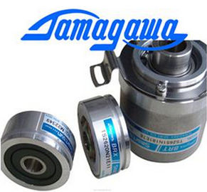
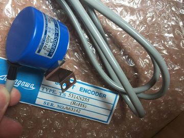
| Brand Name: | Tamagawa |
| Certification: | CE |
| Model Number: | TS5631N224 |
| Minimum Order Quantity: | 1pcs |
|---|---|
| Packaging Details: | carton |
| Delivery Time: | in stock |
| Payment Terms: | T/T, Western Union, MoneyGram |
| Supply Ability: | 100pcs/week |
| TAMAGAWA: | TAMAGAWA | TS5631N224: | TS5631N224 |
|---|---|---|---|
| Japan: | Japan | Color: | Black |
| Wire: | Wire | Material: | Iron |
| Temperature: | 30-80 | Dimension: | 60mm |
| If necessary, open the FB interface editor (may have to click on the small arrow to expand the view). |
In the Retain column for this timer structure, change the selection to "Retain". |
| Under Static, locate the timer structure that was just created for you. | If the FB was created with the "Standard - compatible with S7-300/400" box checked (allows symbolic and direct access): |
| In the Retain column for this timer structure, change the selection to "Retain". | Open the FB for edit. |
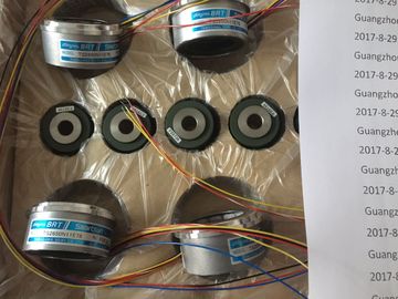
Guang Zhou Lai Jie Electric Co.,LTD
TS5631N224
TS1982N128E6
8001231S
TS3653N4E12
TS5013N64
TS3630N2E3
TS5016N
TS5000N532
TS4231N6E17
TS1982N53E6
800123-2R
TS3653N14E12
TS5420N60
TS3630N2E4
TS5016N60
TS5000N632
TS4231N6E17
TS1982N56E18
TS3653N58E5
Place the timer instruction at the desired location in the FB.
3. When the Call options dialog appears, click on the multi instance icon. The multi instance
option is only available if the instruction is being placed into an FB.
4. In the Call options dialog, rename the timer if desired.
5. Click OK. The timer instruction appears in the editor, and the IEC_TIMER structure
appears in the FB Interface under Static.
6. Open the block that will use this FB.
7. Place this FB at the desired location. Doing so results in the creation of an instance data
block for this FB.
8. Open the instance data block created when you placed the FB in the editor.
9. Under Static, locate the timer structure of interest. In the Retain column for this timer
structure, check the box to make this structure retentiveUse the counter instructions to count internal program events and
external process events. Each counter uses a structure stored in a
data block to maintain counter data. You assign the data block when
the counter instruction is placed in the editor.
CTU is a count-up counter
CTD is a count-down counter
CTUD is a count-up-and-down counterFor LAD and FBD: Select the count value data type from the drop-down list below the instruction name.
2 STEP 7 automatically creates the DB when you insert the instruction.
3 In the SCL examples, "IEC_Counter_0_DB" is the name of the instance DB. The numerical range of count values depends on the data type you select. If the count value is an unsigned integer
type, you can count down to zero or count up to the range limit. If the count value is a signed integer, you can count
down to the negative integer limit and count up to the positive integer limit. The number of counters that you can use in your user program is limited only by the amount
of memory in the CPU. Counters use the following amount of memory:
● For SInt or USInt data types, the counter instruction uses 3 bytes.
● For Int or UInt data types, the counter instruction uses 6 bytes.
● For DInt or UDInt data types, the counter instruction uses 12 bytes
These instructions use software counters whose maximum counting rate is limited by the
execution rate of the OB in which they are placed. The OB that the instructions are placed in
must be executed often enough to detect all transitions of the CU or CD inputs. For faster
counting operations, see the CTRL_HSC instruction (Page 337).
Note
When you place counter instructions in an FB, you can select the multi-instance DB option,
the counter structure names can be different with separate data structures, but the counter
data is contained in a single DB and does not require a separate DB for each counter. This
reduces the processing time and data storage necessary for the counters. There is no
interaction between the counter data structures in the shared multi-instance DBThe CTU counter counts up by 1 when the value of parameter CU
changes from 0 to 1. The CTU timing diagram shows the operation for
an unsigned integer count value (where PV = 3).
If the value of parameter CV (current count value) is greater than or
equal to the value of parameter PV (preset count value), then the
counter output parameter Q = 1.