|
| Place of Origin: | Japan |
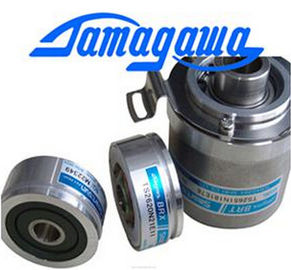
| Brand Name: | Tamagawa |
| Certification: | CE |
| Model Number: | TS5205N454 |
| Minimum Order Quantity: | 1pcs |
|---|---|
| Packaging Details: | carton |
| Delivery Time: | in stock |
| Payment Terms: | T/T, Western Union, MoneyGram |
| Supply Ability: | 100pcs/week |
| TAMAGAWA: | TAMAGAWA | Material: | Iron |
|---|---|---|---|
| Color: | Black | Temperature: | Iron |
| Wire: | Wire | Japan: | Japan |
| TS5205N454: | TS5205N454 | Dimenison: | 40mm |
| Standardization of reference potentials | High-voltage surge protection for RS 485 |
| 7 Blitzductor CT, type B for building | interfaces at transition 0 <--> 1 |
| transitions; order number: 919 506* and |
You can order these components directly aOvervoltage occurs when inductive devices are switched off. Examples are relay |
TS3103N156
TS5205N454
TS3653N2E5
TS5320N510
TS5016N-60
TS5016N60
TS2651N111E78
TS2014N181E32
TS5013N60,
TS5013N61,
TS5016N60,
TS5017N60,
TS5013N68,
TS5
013N69
TS5013N60
TS5016N60
TS5013N60
TS5016N60
TS5017N60
TS5013N68
TS5013N69
TS2014N181E32
TS2014N311E32
TS2650N11E78
TS2650N1E78
TS5081N1
TS5084N250
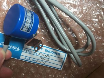
TS5314N255
TS5303N510
TS5622N131
TS1616N200
TS1501N13
TS5641N154
TS5205N454
TS5668N20
TS5667N120
TS5667N420
TS5308N616
TS3462N1E76
coils and contactors
Integrated Surge Arrester
digital output modules are equipped with an integrated surge arrester
Additional Overvoltage Protection
Inductive devices require additional surge arresters only in following cases:
• If SIMATIC output circuits can be switched off by additionally installed contacts
(e.g. relay contacts).
• If the inductive loads are not controlled by SIMATIC modules.
Note: Consult the supplier of the inductors for the ratings of surge suppression
devices.
Example
Figure A-8 shows an output circuit that requires additional surge arresters.Suppression with diodes or Zener diodes exhibits the following characteristics:
• Switching overvoltages can be avoided entirely. A Zener diode has a higher
turn-off voltage.
• High turn-off delay (6 to 9 times higher than without suppressor circuits)
The Zener diode switches off more quickly than a diode circuit.Figure A-10 Suppression with AC-Operated Coils
Suppression with a varistor exhibits the following characteristics:
• The amplitude of the switching overvoltage is limited but not attenuated.
• The steepness of the surge voltage remains the same.
• Low turn-off delay.
Suppression with an RC element exhibits the following characteristics:
• The amplitude and steepness of the switching overvoltage are reduced.
• Low turn-off delayThe notes below apply independent of the type or manufacturer of
the electronic
control.
Reliability
Maximum reliability of SIMATIC devices and components is achieved by
implementing extensive and cost-effective measures during development and
manufacture:
• Use of high-quality components;
• Worst-case design of all circuits;
• Systematic and computer-aided testing of all components;
• Birm-in of all large-scale integrated circuits (e.g. processors, memory, etc.);
• Measures preventing static charge when handling MOS ICs;
• Visual checks at different stages of manufacture;
• Continuous heat-run test at elevated ambient temperature ove a period of
several days;
• Careful computer-controlled final testing;
• Statistical evaluation of all returned systems and components to enable the
immediate initiation of suitable corrective measures;
• Monitoring of major control compoments, using on-line tests (watchdog for the
CPU, etc.).
These measures are referred to in safety technology as basic measures. They
prevent or rectify a large proportion of possible faults.
A higher degree of safety standard applies to all applications and situations where
there is a risk of material damage or injury upon the event of a failure. Special
system-specific regulations are applied to such applications and must be observed
on installing the control system (e.g. VDEE 0116 for burner control systems).
For electronic control equipment with a safety function, the measures that have to
be taken to avoid or correct faults are based on the risks involved in the installation.
As of a certain degree of hazard, the basic measures mentioned above are no
longer sufficient. That is, additional measures (e.g. redundant configurations, tests,
checksums, etc.) must be implemented and certified for the control equipment (DIN
VDE 0801). The prototype of the fail-safe F and FH PLCs were
tested by TÜV (German Institute for Technological Suirveillance), BIA and G EM III;
several certificates have been granted. These are suitable therefore for controlling
and monitoring safety-relevant applications.Most plants contain components for handling safety-relevant functions (e.g.
EMERGENCY-OFF switch, protective gates, two-hand controls). To avoid the need
to examine the entire controller from the aspect of safety, the control system is
usually divided into an area that is safety-relevant and an area that is not
safety-relevant. In the non-safety area, no special demands are placed on the
safety of the control equipment, because any failure in the electronic system will
not influence safety in the installation. In the safety-relevant area, however, it is
only allowed to operate controllers or circuits which satisfy the corresponding
regulations.