|
| Place of Origin: | Japan |
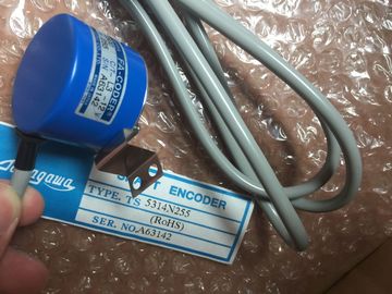
| Brand Name: | Tamagawa |
| Certification: | CE |
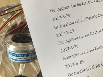
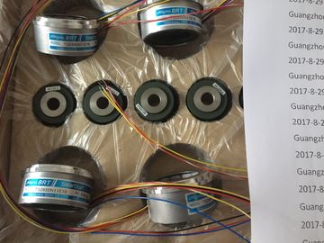
| Model Number: | TS5308N616 |
| Minimum Order Quantity: | 1pcs |
|---|---|
| Packaging Details: | carton |
| Delivery Time: | in stock |
| Payment Terms: | T/T, Western Union, MoneyGram |
| Supply Ability: | 100pcs/week |
| TAMAGAWA: | TAMAGAWA | TS5308N616: | TS5308N616 |
|---|---|---|---|
| Japan: | Japan | Color: | Black |
| Material: | Iron | Temperature: | 20-80 |
| Wire: | Wire | Dimension: | 60mm |
![]()
![]()
![]()
![]()
| conductor and must not be connected to the shield bus. | |
| The outer braided shield serves to discharge interference currents and must be incorporated in shielding and grounding measures. |
|
| In order to avoid ground loops, electronics ground and chassis ground of the monitor must be isolated. |
TS5308N616
TS5308N616
TS2650N11E78
TS5420N60
TS5208N131
TS3462N1E76
48-2500P8-L6-5VC/T-L3-12V
TS-5016N-60
TS5214N561
TS5214N510
TS2014N182E32
TS3653N2E5
TS5320N510
TS5016N-60
TS5016N60
TS5305N616
TS5008N12238
TS5214N564
TS5212N569
TS2651N111E78
TS2014N181E32
TS-5208N130
TS5207N76
TS5246N160
This is achieved by satisfying the following requirement:
• Electronic and chassis grounds of the monitor are isolated from each other.
• Electronic and chassis grounds of the monitor are interconnected via a
voltage-dependent resistor (VDR) fitted by the manufacturer of the monitor.
Assembling and Installing Systems
A-35 Automation System Hardware and Installation
A5E00850741-01
Shielding and Grounding under Industrial Conditions
If the monitor and programmable controller are operated under harsh industrial
conditions, you must observe the following:
On the side of the programmable controller:
• Connect the cable shields in the cabinet to the shielding busbar immediately
behind the cable inlet. The following points are important:
-- Strip the video cables without damaging the conductors.
-- Secure the outer braided shield with the largest possible area to the
shielding busbar of the programmable controller (for example, secure the
shielding with metal straps or cable clamps).
• Provide large-area conta- Strip the video cables without damaging the conductors.
-- Secure the outer braided shield with the largest possible area to the
shielding busbar of the programmable controller (for example, secure the
shielding with metal straps or cable clamps).
• Provide large-area contact between the shielding busbars and the frame or
cabinet wall.
• Connect the shielding busbar to the central grounding point of the cabinet.
On the side of the monitor:
Isolate electronic ground and chassis ground from each other. Proceed as
follows:
-- Remove the jumper on the monitor to separate the two potentials.
-- Install a contact protection on the video sockets, because with isolated
grounding, a shock--hazard voltage of more than 40 V may develop in this
area.
! Caution
There is a risk of personal injury.
Shock-hazard voltages may be present at the video sockets of the monitor.
Insulate the socketsConnect the ground clamp of the monitor to the chassis ground.
• Connect the cable shields to the ground clamp of the monitor as follows:
Proceed as follows:
-- Strip the outer cable insulation of the video cables in the region of the ground
clamp of the monitor, without damaging the braided shield.
-- Secure the outer braided shield over a large area to the ground clamp of the
monitor.All electronic modules are equipped with large-scale integrated ICs or components.
Due to their design, these electronic elements are very sensitive to overvoltages
and thus to any electrostatic discharge.
These Electrostatically-Sensitive Devices are commonly referred to by the
abbreviation ESD.
Electrostatically-sensitive devices are labeled with the following symbol:Caution
Electrostatically-sensitive devices are subject to voltages that are far below the
voltage values that can still be perceived by human beings. These voltages are
present if you touch a component or the electrical connections of a module without
previously being electrostatically discharged. In most cases, the damage caused
by an overvoltage is not immediately noticeable and results in total damage only
after a prolonged period of operation.g
Every person with a non-conductive connection to the electrical potential of its
surroundings is subject to electrostatic charge.
Figure B-1 shows you the maximum values for electrostatic voltages which can
build up on a person coming into contact with the materials indicated in the figure.
These values are in conformity with the specifications of IEC 61000-4-2.General Protective Measures Against Electrostatic
Discharge Damage
Ensure Sufficient Grounding
Make sure that the personnel, working surfaces, and packaging are sufficiently
grounded when handling electrostatically-sensitive devices. You thus avoid
electrostatic charging.
Avoid Direct Contact
You should touch electrostatically-sensitive devices only if it is unavoidable
(for example, during maintenance work). Hold modules without touching the pins of
components or printed conductors. In this way, the discharged energy cannot affect
the sensitive devices.
If you have to carry out measurements on a module, you must discharge your body
before you start the measurement by touching grounded metallic parts. Use
grounded measuring devices onlyAn address is the identifier for a specific area of memory on which an instruction
acts.
Examples: Input I 12.1; Memory Word MW24; Data Block DB3.
Analog Module
Analog modules convert analog process variables (for example, temperature) into
digital values that can be processed in the CPU or they convert digital values into
analog manipulated variables.The backup battery ensures that the user program in the CPU is not lost in the
event of a power failure and that defined data areas, bit memory, timers, and
counters are also retained.
Bit Memory (M)
A memory area in the system memory of a SIMATIC CPU. This area can be
accessed using write or read access (bit, byte, word, and double word). The bit
memory area can be used by the user to store intermediate results. It can be
accessed bit by bit, byte by byte, word by word, or double word by double word.
Building Ground
The connection between data processing equipment and ground, whereby no
unacceptable functional interference to data processing equipment is caused by
external effects, such as interference caused by power systems. The connection
must be in the form of a low-noise ground.Entity of a serial bus system, coupled via repeaters.Programmable module with MPI interface, controls the automation tasks.
Chassis Ground