|
| Place of Origin: | Japan |
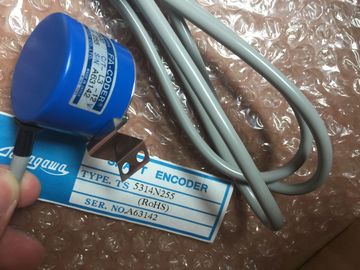
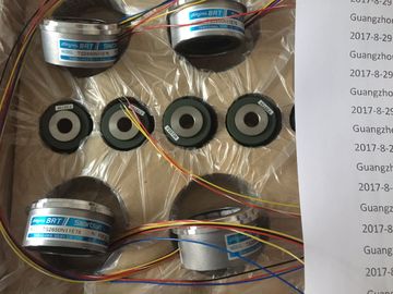
| Brand Name: | Tamagawa |
| Certification: | CE |
| Model Number: | TS5208N131 |
| Minimum Order Quantity: | 1pcs |
|---|---|
| Packaging Details: | carton |
| Delivery Time: | in stock |
| Payment Terms: | T/T, Western Union, MoneyGram |
| Supply Ability: | 100pcs/week |
| TAMAGAWA: | TAMAGAWA | Temperature: | 20-80 |
|---|---|---|---|
| Color: | Black | Material: | Iron |
| TS5208N131: | TS5208N131 | Wire: | Wire |
| Dimension: | 60mm |
| event in the process. The hardware interrupt is signalled to the CPU. | |
| In accordance with the priority of this interrupt, the corresponding organization block is then executed. |
|
| Instance Data Block With the , each call of a function block in the STEP 7 user program is |
TS3103N156
TS5208N131
TS3653N1E2
TS5667N120
TS3624N2E3
TS3738N1E7
TS2151N1E45
TS3699N232
TS3653N3E9
2000144
TS3653N2E4
TS5778N155
TS3624N2E4
TS4559N3E15
TS2151N11E45
TS3738N1E7
TS1980N43E12
482048P6L65V
TS3653N2E5
TS5778N157
TS3624N3E5
TS4886N9079E411
TS2640N321E64
TS3738N1E7
TS1980N56E12
assigned a data block which is generated automatically. In the instance data block,
the values of the input, output and in/out parameters as well as the local block data
are stored.
Interface, Multipoint
→ Multipoint Interface.
Interrupt, Cyclic
→ Cyclic Interrupt
Isolated
In the case of isolated I/O modules, the reference potentials of the control and load
circuits are galvanically isolated from each other, for example, by optocouplers,
relay contacts, or transformers. The I/O circuits can be connected to a common
potential.The load memory is part of the CPU. It contains objects created by the
programming device. It can be either a plug-in memory card or an integrated
memory.
Contains the complete user program during runtime, the comments and the
symbolic system, additional special information which allows decompilation of the
user program, and all module parameters.
Local Data
→ Data, Temporary
Logic Block
In SIMATIC S7, a logic block is a block that contains part of the STEP 7 user
program. The other type of block is a data block which contains only data.
M
Manufacturer--specific interrupt
Can be generated by a DPV1 slave. The DPV1 master responds with a call of
OB57.
For detailed information on OB57, refer to the “System Software for S7-300/
System and Standard Functions” reference manual.
Measuring Range Submodule
Measuring range submodules are plugged onto the analog input module for
adapting to various measuring ranges.The multipoint interface is the programming device interface in SIMATIC S7. It
enables the simultaneous operation of a number of nodes (programming devices,
text display operator interfaces, and operator panels) from one or more CPUs.
Each node is identified by an address (MPI address).
MPI Address
→ Multipoint Interface (MPI)
N
Nesting Depth
A block can be called from another block by means of block calls. The nesting
depth is the number of simultaneously called logic blocks.
Network
In communications, a network is the connection between two or more
CPUs and other terminals such as a programming device, via a connecting cable.
Data are exchanged over the network between the connected stations.
Node Number
The node number represents the accessing address of a CPU or programming
device or of another intelligent I/O module when they communicate with each other
via a network. The node number is assigned by the CPU or programming device
using the STEP 7 software.
Non-Isolated
In the case of non-isolated I/O modules, the reference potentials of the control and
load circuits are electrically connected to each otherOrganization Block
OB Priority
The operating system of the CPU differentiates between various priority
classes, for example, cyclic program processing, process interrupt-controlled
program processing. Each priority class is assigned organization blocks (OBs),
where the S7 user can program a reaction. As a standard, the OBs have different
priorities to which they are processed when they occur simultaneously or when
they interrupt each other.
Operating State
The SIMATIC S7 programmable controllers recognize the following operating
states: STOP, STARTUP, RUN.
Operating System of the CPU
The operating system of the CPU organizes all functions and sequences of the
CPU which are not connected to a specific control task.
Organization Block (OB)
Organization blocks form the interface between the operating system of the
CPU and the user program. The sequence in which the user program should be
processed is laid down in the organization blocks.Variable of a STEP 7 logic block
2. Variable for setting the reaction of a module (one or more per module).