 |
| Place of Origin: | Japan |
| Brand Name: | Tamagawa |
| Certification: | CE |
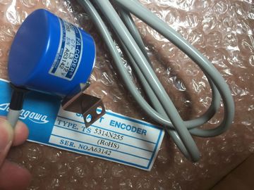
| Model Number: | TS5016N60 |
| Minimum Order Quantity: | 1pcs |
|---|---|
| Packaging Details: | carton |
| Delivery Time: | in stock |
| Payment Terms: | T/T, Western Union, MoneyGram |
| Supply Ability: | 100pcs/week |
| TAMAGAWA: | TAMAGAWA | Material: | Iron |
|---|---|---|---|
| Japan: | Japan | Color: | Black |
| Temperature: | 20-80 | Wire: | Wire |
| Dimension: | 50mm | TS5016N60: | TS5016N60 |
| Parameters can be static or dynamic. | |
| Parameters, Dynamic | |
| n contrast to static parameters, dynamic parameters of modules can be changed during operation by calling an SFC in the user program, for example, limit values of an analog signal input module. |
TS3103N156
TS-5016N-60
TS3762N15E4
TS1981N56E19
TS3653N3E9
TS5850N70
TS3630N1306
TS5013N69
TS2650N101E78
TS4126N1017E235
TS1981N56E19
TS3653N13E9
TS5N2E18
TS3630N1E1
TS5013N61
TS2651N111E78
TS4127N1017E215
TS1982N126E6
TS3653N44E8
TS3630N1E2
TS5013N89
TS2651N181E78
TS4127N1017E235
TS1982N128E6
8001231S
Organization Block (OB)
Organization blocks form the interface between the operating system of the
CPU and the user program. The sequence in which the user program should be
processed is laid down in the organization blocks.Variable of a STEP 7 logic block
2. Variable for setting the reaction of a module (one or more per module).
Parameters can be static or dynamic.
Parameters, Dynamic
In contrast to static parameters, dynamic parameters of modules can be changed
during operation by calling an SFC in the user program, for example, limit values of
an analog signal input module.
In contrast to dynamic parameters, static parameters of modules cannot be
changed by means of the user program, but only via STEP 7 (not in the RUN
state); for example, input delay of a digital signal input module.
PG
→ Programming Device
PROFIBUS DP
Digital, analog and intelligent modules, as well as a wide range of field devices to
EN 50170, Part 3, such as drives or valve modules are moved to the local process
by the PLC across distances of up to 23 km.
The modules and field devices are interconnected with the PLC via PROFIBUS DP
field bus and are addressed in the same way as local I/O.
Priority classes
The S7 CPU operating system provides up to 26 priority classes (or “program
execution levels”) which are assigned different OBs. These classes determine
which OB can interrupt other OBs. Several OBs belonging to the same priority
class do not interrupt each other, and are executed in sequential order.
Process Image
The process image is a component part of the system memory of the CPU.
At the beginning of the cyclic program, the signal states of the input modules are
transferred to the process-image input table (PII). At the end of the cyclic program,
the process-image output table (PIQ) is transferred to the output modules as the
signal state.
Programming Device (PG)
A personal computer with a special compact design, suitable for industrial
conditions. A programming device is completely equipped for
programming the SIMATIC programmable logic controllers.
Protective Ground
Connection via protective conductor to a common ground conductor for the
exposed, conductive parts of electrical apparatus which are not normally live, but at
which a voltage may be present in the event of a fault, and which are jointly
protected via a protective device
The RAM (Random Access Memory) is a semiconductor memory with random
access (read/write memory). May be used as for storing interim data for later use.
This memory is not retentive, that is, its data are lost after power failure.
Reference Ground
→ Ground
Reference Potential
The potential on which the voltages of the various circuits are based and according
to which they are measured.
Retentive Data
Retentive data are not lost after a power failure, if a backup battery is provided.
Release version
Used to distinguish products with the same order number. Incremented with each
up-compatible functional enhancement, manufacturing-specific change (use of new
parts / components) and for bugfixes.
Run-Time Error
Errors that occur in the programmable controller (that is, not in the process) during
execution of the user program.
The scan cycle time is the time the CPU takes to run the user program once
through.
Shared Data
Shared data can be accessed by any code block (FC, FB, OB). These include bit
memory M, inputs I, outputs Q, timers T, counters C, and data blocks DB. Global
data can be accessed either absolutely or symbolically.Signal modules (SMs) are the interface between the process and the
programmable controller. Signal modules comprise digital input and output
modules (I/O module, digital) and analog input and output modules (I/O module,
analog).
Slave
A slave may only exchange data when requested by a master.
STARTUP
The CPU goes through the STARTUP state during the transition from STOP to
RUN mode. It can be set using the mode selector on the CPU, following power-on,
or by an operation on the programming device.
Status interrupt