 |
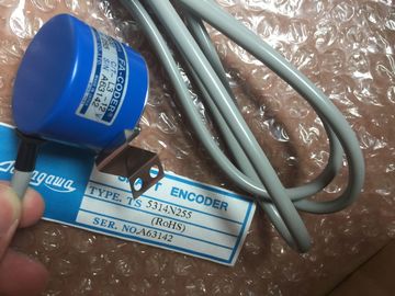
| Place of Origin: | Japan |
| Brand Name: | Tamagawa |
| Certification: | CE |
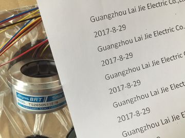
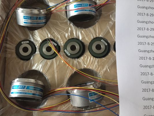
| Model Number: | TS5016N60 |
| Minimum Order Quantity: | 1pcs |
|---|---|
| Packaging Details: | carton |
| Delivery Time: | in stock |
| Payment Terms: | T/T, Western Union, MoneyGram |
| Supply Ability: | 100pcs/week |
| TAMAGAWA: | TAMAGAWA | TS5016N60: | TS5016N60 |
|---|---|---|---|
| Japan: | Japan | Color: | Black |
| Material: | Iron | Temperature: | 20-80 |
| WIRE: | Wire | Dimension: | 40mm |
| Remove the module straight up from its mounting position in the top of the CPU. |
In the BB 1297, install a new battery with the positive side of the battery on top, and the |
| Replace the cover onto the CPU. | negative side next to the printed wiring board. The BB 1297 requires battery type CR1025. The battery is not included with the BB 1297 |
| Replace the terminal block covers.The BB 1297 requires battery type CR1025. The battery is not included with the BB 1297 | and must be purchased by the user. To install or replace the battery, follow these steps: |
TS3103N156
TS5016N60
TS5208N576
TS4503N1022E200
TS3103N156
FACODER
TS3664N2E3
TS5013N60
TS3641N22E7
TS5208N68
TS5210N450
TS4503N1202E200
TS3103N178
TS3664N2E4
TS5013N61
TS3641N2E3
TS5212N351
TS5210N453
TS4503N1205E200
TS3103N255
TS3664N50
TS5016N60
TS3641N12E3
TS5212N510
nd must be purchased by the user. To install or replace the battery, follow these steps:
1. In the BB 1297, install a new battery with the positive side of the battery on top, and the
negative side next to the printed wiring board. Install your SM after installing the CPU.
1. Ensure that the CPU and all equipment are
disconnected from electrical power.
2. Remove the cover for the connector from the right side of the
CPU.
3. Insert a screwdriver into the slot above the cover.
4. Gently pry the cover out at its top and remove the cover.
Retain the cover for reuse.
Connect the SM to the CPU:
1. Position the SM beside the CPU.
2. Hook the SM over the top of the DIN rail.
3. Pull out the bottom DIN rail clip to allow the SM to fit over the
rail.
4. Rotate the SM down into position beside the CPU and push
the bottom clip in to latch the SM onto the rail.
Extending the bus connector makes both mechanical and electrical connections for
the SM.
1. Place a screwdriver beside the tab on the top of the SM.
2. Slide the tab fully to the left to extend the bus connector into the CPU.
Follow the same procedure to install a signal module to a signal module. You can remove any SM without removing the CPU or other SMs in place.
1. Ensure that the CPU and all equipment are disconnected from
electrical power.
2. Remove the I/O connectors and wiring from the SM (Page 55).
3. Retract the bus connector.
– Place a screwdriver beside the tab on the top of the SM.
– Press down to disengage the connector from the CPU.
– Slide the tab fully to the right.
If there is another SM to the right, repeat this procedure for that SM.
Remove the SM:
1. Pull out the bottom DIN rail clip to release the SM from the rail.
2. Rotate the SM up and off the rail. Remove the SM from the system.
3. If required, cover the bus connector on the CPU to avoid contamination.
Follow the same procedure to remove a signal module from a signal module.
3.3.5 Installing and removing a CM or CP
Attach any communication modules to the CPU and install the assembly as a unit, as shown
in Installing and removing the CPU (Page 49)1. Ensure that the CPU and all equipment are
disconnected from electrical power.
2. Attach the CM to the CPU before installing the assembly
as a unit to the DIN rail or panel.
3. Remove the bus cover from the left side of the CPU:
– Insert a screwdriver into the slot above the bus cover.
– Gently pry out the cover at its top.
4. Remove the bus cover. Retain the cover for reuse.
5. Connect the CM or CP to the CPU:
– Align the bus connector and the posts of the CM with
the holes of the CPU
– Firmly press the units together until the posts snap into
place.
6. Install the CPU and CP on a DIN rail or panel. Remove the CPU and CM as a unit from the DIN rail or panel.
1. Ensure that the CPU and all equipment are disconnected from electrical
power.
2. Remove the I/O connectors and all wiring and cables from the CPU and CMs.
3. For DIN rail mounting, move the lower DIN rail clips on the CPU and CMs to the
extended position.
4. Remove the CPU and CMs from the DIN rail or panel.
5. Grasp the CPU and CMs firmly and pull apart. The CPU, SB and SM modules provide removable connectors to make connecting the wiring
easy.
Table 3- 10 Removing the connector
Task Procedure
Prepare the system for terminal block connector removal by removing the power from the
CPU and opening the cover above the connector.
1. Ensure that the CPU and all equipment are disconnected from electrical power.
2. Inspect the top of the connector and locate the slot for the tip of the screwdriver.
3. Insert a screwdriver into the slot.
4. Gently pry the top of the connector away from the CPU. The connector will release with a
snap.
5. Grasp the connector and remove it from the CPUPrepare the components for terminal block installation by removing power from the CPU and
opening the cover for connector.
1. Ensure that the CPU and all equipment are disconnected from electrical power.
2. Align the connector with the pins on the unit.
3. Align the wiring edge of the connector inside the rim of the connector base.
4. Press firmly down and rotate the connector until it snaps into place.
Check carefully to ensure that the connector is properly aligned and fully engaged. The expansion cable provides additional flexibility in configuring the layout of your
system. Only one expansion cable is allowed per CPU system. You install the
expansion cable either between the CPU and the first SM, or between any two SMs.To install the male connector:
1. Ensure that the CPU and all equipment are disconnected
from electrical power.
2. Push the connector into the bus connector on the right side of the
signal module or CPU.
To remove the male connector:
1. Ensure that the CPU and all equipment are disconnected
from electrical power.
2. Pull out the male connector to release it from the signal module or
CPU. 1. Ensure that the CPU and all equipment
are disconnected from electrical power.
2. Place the female connector to the bus connector on
the left side of the signal module.
3. Slip the hook extension of the female connector
into the housing at the bus connector and press