 |
| Place of Origin: | Japan |
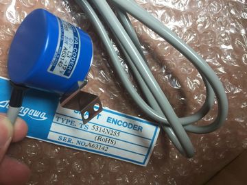
| Brand Name: | Tamagawa |
| Certification: | CE |
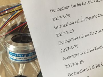
| Model Number: | TS5008N12238 |
| Minimum Order Quantity: | 1pcs |
|---|---|
| Packaging Details: | carton |
| Delivery Time: | in stock |
| Payment Terms: | T/T, Western Union, MoneyGram |
| Supply Ability: | 100pcs/week |
| TAMAGAWA: | TAMAGAWA | TS5008N12238: | TS5008N12238 |
|---|---|---|---|
| Temperature: | 20-80 | Color: | Black |
| Material: | Iron | Wire: | Wire |
| Japan: | Japan | Dimension: | 50mm |
| You can access the "Change call type" command either | Options" menu. The "Call options" dialog allows |
| y right-clicking the instruction or FB in the program | ou to select a single-instance or multi-instance DB. You can |
| editor or by selecting the "Block call" command from the | also select specific DBs from a drop-down list of available DBs.You can disconnect individual network devices from the subnet. Because the configuration of |
TS3103N156
TS5008N12238
TS5013N63
TS3641N32
TS5213N550
TS5210N530
TS4503N2000E100
TS3103N40
OAS66
TS3667N11E2
TS5016N61
TS3641N38
TS5213N551
TS5210N54
TS4503N2070E100
TS3132N32
OAS66
TS1857N16EP
TS3667N2E5
TS5016N63
TS3643N2
TS5308N510
TS20E12
TS4503N2202E200
TS3134N21
the device is not removed from the project, you can easily restore the connection to the
device. Right-click the interface port of the network
device and select the "Disconnect from
subnet" command from the context menu. STEP 7 reconfigures the network connections, but does not remove the disconnected device
from the project. While the network connection is deleted, the interface addresses are not
changedWhen you download the new network connections, the CPU must be set to STOP mode.
To reconnect the device, simply create a new network connection to the port of the device. STEP 7 provides a storage area for
"unplugged" modules. You can drag a
module from the rack to save the
configuration of that module. These
unplugged modules are saved with your
project, allowing you to reinsert the
module in the future without having to
reconfigure the parameters.
One use of this feature is for temporary
maintenance. Consider a scenario where
you might be waiting for a replacement
module and plan to temporarily use a
different module as a short-term
replacement. You could drag the
configured module from the rack to the
"Unplugged modules" and then insert the
temporary module. As a general rule for laying out the devices of your system, always separate the devices that
generate high voltage and high electrical noise from the low-voltage, logic-type devices such
as the .
When configuring the layout of the inside your panel, consider the heat-generating
devices and locate the electronic-type devices in the cooler areas of your cabinet. Reducing
the exposure to a high-temperature environment will extend the operating life of any
electronic device.
Consider also the routing of the wiring for the devices in the panel. Avoid placing low-voltage
signal wires and communications cables in the same tray with AC power wiring and highenergy,
rapidly-switched DC wiring devices are designed for natural convection cooling. For proper cooling, you must
provide a clearance of at least 25 mm above and below the devices. Also, allow at least 25
mm of depth between the front of the modules and the inside of the enclosure.
When planning your layout for the system, allow enough clearance for the wiring
and communications cable connections. When planning your layout for the system, allow enough clearance for the wiring
and communications cable connections. If you require an external 24 VDC power supply, ensure that the power supply is not
connected in parallel with the sensor supply of the CPU. For improved electrical noise
protection, it is recommended that the commons (M) of the different power supplies be
connected.
WARNING
Connecting an external 24 VDC power supply in parallel with the 24 VDC sensor supply
can result in a conflict between the two supplies as each seeks to establish its own
preferred output voltage level.
The result of this conflict can be shortened lifetime or immediate failure of one or both
power supplies, with consequent unpredictable operation of the PLC system. Unpredictable
operation could result in death, severe personal injury and/or property damage.
The DC sensor supply and any external power supply should provide power to different
points. Some of the 24 VDC power input ports in the system are interconnected, with a
common logic circuit connecting multiple M terminals. For example, the following circuits are
interconnected when designated as "not isolated" in the data sheets: the 24 VDC power
supply of the CPU, the power input for the relay coil of an SM, or the power supply for a nonisolated