|
| Place of Origin: | Japan |
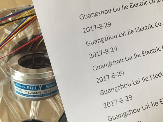
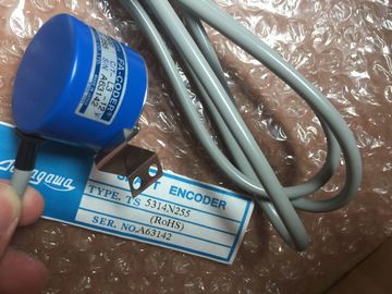
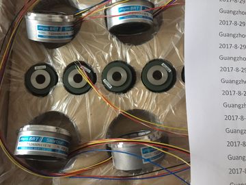
| Brand Name: | Tamagawa |
| Certification: | CE |
| Model Number: | TS5212N569 |
| Minimum Order Quantity: | 1pcs |
|---|---|
| Packaging Details: | carton |
| Delivery Time: | in stock |
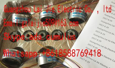
| Payment Terms: | T/T, Western Union, MoneyGram |
| Supply Ability: | 100pcs/week |
| TAMAGAWA: | TAMAGAWA | Material: | Iron |
|---|---|---|---|
| Color: | Black | Japan: | Japan |
| TS5212N569: | TS5212N569 | Temperature: | 20-70 |
| Wire: | Wire | Dimension: | 50mm |
| insulating collar to | with or without |
| DIN 46228, shape A, | insulating collar to |
| short version | DIN 46228 Part 1 |
TS3103N156
TS5212N569
TS3134N22
OIS1000CT3L5V108
TS3667N3E7
TS5017N60
TS3643N233E8
TS5312-N250
TS2151N141E9
TS4506N1202E200
TS3134N317
OSE10243158
TS3667N3E8
TS5019N60
TS3653N11E2
TS5313N122
TS2228N33E1
TS4507N1002E200
TS3134N52
OSE5K-6-12-108
TS3667N13E8
TS5013N68
TS3653N12E5
r 4, Shape A,
normal version
with or without
insulating collar to
DIN 46228 Part 1 or
4, Shape A, normal
version
Blade width and
shape of the screw
driver
3.5 mm (cylindrical
shape)
- 3.5 mm (cylindrical
shape)
0.5 mm x 3.5 mm
DIN 5264
Tightening torque:
for connecting
conductors
0.6 to 0.8 Nm - 0.6 to 0.8 Nm -
* You can also connect a bination of two conductors of up to 1.0 mm each to a screw-type
or spring-loaded terminal. You must use special wire end ferrules for this purpose. Two types
and manufacturers of such ferrules are given below:
• Phoenix TWIN Type no. 32 00 81 0, for 2 x 1 mm2
• AMP Order no. 966 144-4, for 2 x 1 mm2
Note
You must use shielded cables for the analog modules (see Section A.5).You use the power supply connector to connect a power supply module to your
supply. When delivered, the power supply connector is plugged into the power
supply module. There are two versions (AC and DC) of power supply connector.
The two versions are coded, meaning an AC connector can only be plugged into
an AC power supply module, and a DC connector can only be plugged into a DC
power supply module.
Disconnecting the Power Supply Connector
Before wiring, you must unplug the power supply connector from the power supply
module.
1. Open the cover of the power supply module.
2. Detach the connector by levering it off with a suitable tool, for example, a
screwdriver, at the opening provided (1).
3. Pull the connector forward and out of the power supply moduleTo wire the power supply connector, follow the steps outlined below:
! Warning
There is a risk of personal injury.
If you wire the connector with voltage applied, you may suffer a shock and
personal injury.
Only wire the connector with power disconnected.
1. Switch off the line voltage at your VAC supply disconnector.
Note
The standby switch of the power supply module does not disconnect the power
supply module from the supply.
2. Are you using a flexible sheathed cable with outer insulation (with 230 VAC)?
If so: Strip the outer insulation over a length of 70 mm. Note that an overall
cable diameter of between 3 mm and 9 mm must be present under the strain
relief after connection.
If not: Wrap the cores with insulating tape so that an overall cable diameter of
between 3 mm and 9 mm will be present under the strain relief after connection.
As an alternative to insulating tape, you can use a shrink-on sleeve.
3. Shorten the two cores which are not needed for connection to protective ground
(PE) by 10 mm.
4. Strip the cores over a length of 7 mm.
5. Slacken the screw in the cover of the power supply connector and open the
connector6. Slacken the screw of the strain relief and insert the cable.
7. Connect the cores according to the illustration on the cover of the power supply
connector. Connect the longer core to PE. Screw on the cores with a torque of
0.6 to 0.8 N/m.Figure 4-10 Wiring the power supply connector
8. Tighten the screw of the strain relief, so that the cable is secured properly.
9. Close the power supply connector and screw on the cover.
! Caution
The power supply module or power supply connector can be damaged.
If you plug in or disconnect the connector with voltage applied, the power supply
module or the connector may be damaged.
Only plug in or disconnect the power supply connector with power removed.In the Power Supply Connector
You can only plug in the connector when the power supply module is installed
(lower mounting screw tightened).
To plug the wired power supply connector into the power supply module, follow the
steps outlined below:
1. Open the cover of the power supply module.
2. Insert the power supply connector into the guide groove in the module housing.
3. Slide the power supply connector into the power supply module as far as it will
travel.
4. Close the cover of the power supply module.
The following figure shows how to plug the power supply connector into the power
supply moduleHow to connect your sensors and actuators to the signal modules:
1. Wire the front connector.
This includes all ining and outgoing connections of the sensorsan actuators.
2. Install the front connector on the module.
The Three Types of Front Connector