 |
| Place of Origin: | Japan |
| Brand Name: | Tamagawa |
| Certification: | CE |
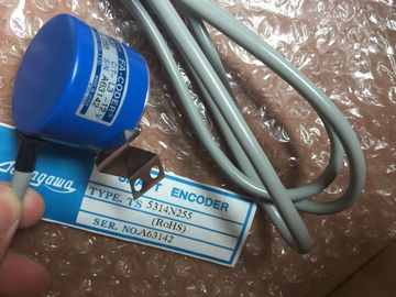
| Model Number: | TS2651N111E78 |
| Minimum Order Quantity: | 1pcs |
|---|---|
| Packaging Details: | carton |
| Delivery Time: | in stock |
| Payment Terms: | T/T, Western Union, MoneyGram |
| Supply Ability: | 100pcs/week |
| Tamagawa: | Tamagawa | TS2651N111E78: | TS2651N111E78 |
|---|---|---|---|
| COLOR: | Black | Material: | Iron |
| Temperature: | 20-70 | Wire: | Wire |
| Dimension: | 50mm | Japan: | Japan |
| Are you using wire ferrules? | |
| If yes: Strip the conductors at a length of 10 mm. Press-fit the wire end ferrules onto the conductors. |
|
| If not: Strip the conductors at a length of 8 to 10 mm. |
TS3103N156
TS2651N111E78
TS5313N122
TS2228N33E1
TS4507N1002E200
TS3134N52
OSE5K-6-12-108
TS3667N13E8
TS5013N68
TS3653N12E5
TS5320N632
TS2640N141E172
TS4507N1202E200
OSE5KN-6-12-108
TS3674N37
TS5013N69
TS3653N13E8
TS5420
TS2640N181E100
TS4507N1205E200
TS3166N43
TS3679N2E1
TS5208N131
TS3653N1E1
Three types of front connector are available for the signal modules:
• Front connector with crimp terminals
• Front connector with screw terminals
• Front connector with spring loaded terminals.o Wire the Front Connector
1. Insert a screwdriver at the point marked on the bottom left of the front
connector, then lever off the lower corner of the cover.
2. Open the cover pletely.
3. Pull the opened cover forward at the bottom and swing it up.Cut the wires to length. Avoid any loops in the front connector after wiring.
5. Strip the wires according to the table in Section 4.11.
Note
The front connector contains a jumper which is required to enable specific
functions on certain signal modules. Do not remove this jumperure
To wire the prepared front connector:
1. Strip the conductors at a length of approx. 5 mm.
2. Crimp the contacts onto the conductors. A crimptool is aailable on order as an
accessory for your signal modules.
3. Insert the crimp contacts into the recesses of the front connector, starting at the
bottom.
The order number for crimp contacts is found in Appendix C of the Reference
Manual.
To wire the prepared front connector:
1. Are you using wire ferrules?
If yes: Strip the conductors at a length of 10 mm. Press-fit the wire end ferrules
onto the conductors.
If not: Strip the conductors at a length of 8 to 10 mm.
2. Terminate the wires, starting at the bottom of the front connector.
3. Screw the ends of the conductors onto the front connector (tightening torque =
0.6 to 0.8 N/m. Also tighten the unwired terminals
o wire the prepared front connector, follow the steps outlined below:
1. Are you using wire end ferrules?
If so: Strip the conductors over 10 mm. Press-fit the wire end ferrules onto the
conductors.
If not: Strip the conductors over 8 to 10 mm.
2. Use a screwdriver (0.5 x 3.5 mm DIN 5264) to release the spring contact of the
first terminal. Start at the bottom of the front connector.
You can release the individual spring contacts at three points: from the front,
from the side or from the back (see Figure 4-15 ).
3. Push the first wire into the released spring contact and withdraw the
screwdriver.
4. Repeat steps 3 and 4 for all other wires.
The following figure shows the princip
When you have wired the front connector, the cable tie provided should be fitted at the bottom of the front connector as a strain relief for the connected cable. There are three ways of fitting the strain relief, according to the thickness of the cable. Three openings are provided at the bottom of the front connector.