|
| Place of Origin: | Japan |
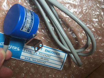
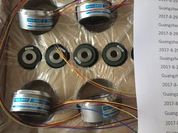
| Brand Name: | Tamagawa |
| Certification: | CE |
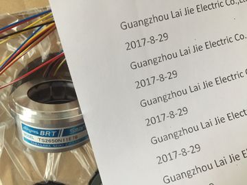
| Model Number: | TS2014N181E32 |
| Minimum Order Quantity: | 1pcs |
|---|---|
| Packaging Details: | carton |
| Delivery Time: | in stock |
| Payment Terms: | T/T, Western Union, MoneyGram |
| Supply Ability: | 100pcs/week |
| TAMAGAWA: | TAMAGAWA | TS2014N181E32: | TS2014N181E32 |
|---|---|---|---|
| Japan: | Japan | Color: | Black |
| Material: | Iron | Temperature: | 20-80 |
| Wire: | Wire | Dimension: | 40mm |
| If the battery error cannot be cleared, try again after a few minutes. | |
| If the battery error still cannot be cleared, remove the battery/batteries and short-circuit it/them for one to three seconds maximum. |
|
| Reinsert the battery/batteries and try to acknowledge with the FMR button again |
TS3103N156
TS2014N181E32
TS3653N13E8
TS5420
TS2640N181E100
TS4507N1205E200
TS3166N43
TS3679N2E1
TS5208N131
TS3653N1E1
TS5641N150
TS2640N321E64
TS4507N1229E200
TS3212N32
RFH102422
TS3679N3E1
TS5208N111E78
TS3617N47E4
TS1508N211
TS2650N11E78
TS4507N2000E100
TS3214N12
RFH1024-22-1M-68
If the battery error message goes off, the battery/batteries is/are operational.
• If the battery error message does not go off, the battery/batteries is/are
discharged.
Removing a Backup Battery
Chapter 7 describes how to remove the backup battery (batteries).
This section describes the procedure for starting up a PROFIBUS-DP subnet with
an CPU as the DP master.
Requirements
Before you can start up the PROFIBUS-DP subnet, the following requirements
must be met:
• The PROFIBUS-DP subnet has been set up (see Chapter 5).
• With STEP 7, you have configured the PROFIBUS-DP subnet and assigned a
PROFIBUS-DP address and the address area to all nodes (see manual
Configuring Hardware and Communication Connections with STEP 7). Note that
for some DP slaves, address switches must also be set (see the reference
manuals for the particular DP slaves).
Starting Up
1. Use the programming device to load the configuration of the PROFIBUS-DP
subnet created under STEP 7 (preset configuration) in the CPU. This procedure
is described in the manual Configuring Hardware and Communication
Connections with STEP 7.
2. Switch on all DP slaves.
3. Switch the CPU from STOP to RUN.
Behavior of the CPU During Startup
During startup, the CPU compares the preset and actual configurations. You set
the duration of the test with STEP 7 in the “Startup” parameter block with the
“module time limits” parameter. (See also Reference Manual, Chapter 1, the
manual Configuring Hardware and Communication Connections with STEP 7, and
the STEP 7 Online Help).
If the preset configuration = actual configuration, the CPU goes into RUN.
If the preset configuration ≠ actual configuration, the CPU’s reaction depends on
the setting of the parameter for “Startup if preset configuration ≠ actual
configuration”:
Startup if Preset Config. Actual
Config. = Yes (Default)
Startup if Preset Config. ≠ Actual Config. = No
CPU goes into RUN The CPU remains at STOP and, after the timeset in the “module time
limits” parameter, the BUSF LED flashes.
Flashing of the BUSF LED indicates that at least one slave will not
respond. In this case, check whether all slaves are switched on or
display the content of the diagnostic buffer
see Configuring Hardware and Communication Connections with
STEP 7).
Only use interface submodules that are explicitly released for use in
devices.
Installing Interface Modules
! Warning
The modules can be damaged.
When inserting or removing interface submodules with power applied, the CPU
and interface submodules can be damaged (exception: using synchronization
submodules in an H system).
Never insert or remove the interface submodules while power is being supplied
(exception: synchronization submodules). Always switch off the power supply
before inserting or removing interface submodules.
! Caution
Danger of damage to persons and property.
Interface submodules contain electronically-sensitive components that may be
damaged if they are touched.