 |
| Place of Origin: | Japan |
| Brand Name: | Tamagawa |
| Certification: | CE |
| Model Number: | TS5208N130 |
| Minimum Order Quantity: | 1pcs |
|---|---|
| Packaging Details: | carton |
| Delivery Time: | in stock |
| Payment Terms: | T/T, Western Union, MoneyGram |
| Supply Ability: | 100pcs/week |
| Tamagawa: | Tamagawa | Japan: | Japan |
|---|---|---|---|
| TS5208N130: | TS5208N130 | Material: | Iron |
| Color: | Black | Wire: | Wire |
| Temperature: | 30-80 | Dimension: | 20mm |
TS3103N156
TS-5208N130
TS3679N3E1
TS5208N111E78
TS3617N47E4
TS1508N211
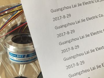
TS2650N11E78
TS4507N2000E100
TS3214N12
RFH1024-22-1M-68
TS3682N1
TS3617N1E1
TS3624N1E1
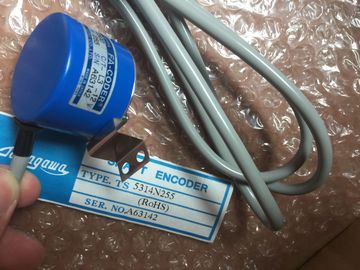
TS1508N255
TS2651N111E78
TS4507N2070E100
TS3214N13
RFH102422IM
TS3682N2
TS3617N1E2
TS3624N21E1
TS1508N257
TS26541N131E78
TS4507N2405E200
TS3214N15
![]()
![]()
![]()
![]()
| Disconnect the power supply connector from the power supply module. | Attach the new module of the same type and swing it downwards. |
| Loosen the mounting screws of the module. | Screw the module on. |
| Swing the module outCheck the voltage selector switch. | Screw the module on. |
Plug in the power supply connector at the power supply module.
6. Insert the backup battery/batteries, if applicable.
7. Close the cover.
8. Set the power disconnector to ON.
9. Set the standby switch of the power supply module to I (output voltages at rated
value).
10.Set the CPU mode switch to RUN if applicable.
How the Behaves after Exchanging Modules
If an error occurs after replacing a module, you can read out the cause of the error
from the diagnostic buffer.If you have provided the modules in your system with slot numbering, you must
remove the number from the old module when replacing it and apply the number to
the new module.
Saving the Data
Save the user program including configuration data.
Removing the Module
1. Set the CPU mode switch to STOP.
2. Set the standby switch of the power supply module to (0 V output voltages).
3. Remove the cover of the CPU.
4. Disconnect the MPI connector, if applicable.
5. Disconnect the connector at the EXT. BATT. socket, if applicable.
6. Remove the memory card.
7. Loosen the mounting screws of the module.
8. Swing the module ouAttach the new module of the same type and swing it downwards.
2. Screw the module on.
3. If applicable, plug the connector for the external battery supply into the socket.
4. Set the CPU mode switch to STOP.
5. Insert the memory card.
6. Set the standby switch of the power supply module to I (output voltages at rated
value).
The remaining procedure depends on whether you use a Flash card and
whether or not you have configured your system for networking.
7. Proceed as follows to operate with a Flash card:
Transfer the user and configuration data.
Set the CPU mode switch to RUN.
Close the cover.
8. If your system is not configured for networking, proceed as follows:
Transfer the user and configuration data by means of the programming device,
via the programming device cable (see Section 6.3).
Set the CPU mode switch to RUN.
Close the cover.
9. If your system is configured for networking, proceed as follows:
Transfer the user and configuration data by means of the programming device,
via the programming device cable (see Section 6.3).
Set up your network by plugging in the MPI connector.
Set the CPU mode switch to RUN.
Close the cover.
How the Behaves after Exchanging Modules
If an error occurs after replacing a module, you can read out the cause of the error
from the diagnostic buffer.If you have provided the modules in your system with slot numbering, you must
remove the number from the old module when replacing it and apply the number to
the new module.
Installing a Module
1. You can replace analog and digital modules in RUN mode. You must have taken
the appropriate action in your STEP 7 program to ensure correct responses
from your system.
If you are not sure whether your program will react correctly, set the CPU mode
switch to STOP.
Improper handling of the front connectors can result in injury and damage.
If the front connector is removed and inserted during operation, hazardous
voltages of >25 VAC or >60 VDC may be present at the pins of the module.
When such voltages are present at the front connector, modules with power
applied may only be replaced by electrical specialists or trained personnel in such
a way that the pins of the module are not touched.
2. Loosen the mounting screw of the front connector and pull it off.
3. Loosen the mounting screws of the module.
4. Swing the module out.
Note
In order that the removal and insertion of digital or analog modules can be
detected by the CPU, a minimum time of two seconds must elapse between
removal and insertionBefore fitting the front connector, you must remove (break off) the front part of the
coding key, because this part is already fitted in the wired front connector.
! Caution
The module can be damaged.
If, for example, you insert a front connector of a digital module in an analog
module, the module may be damaged.
Only operate modules with their complete front connector coding key.
Installing a New Module
1. Attach the new module of the same type at the appropriate slot and swing it
downwards.
2. Screw the module on with both mounting screws.
3. Fit the front connector.
4. If you have set the CPU to STOP, you must now set it to RUN again.
5. After fitting, each programmable module will be reinitialized by the CPU with
parameters.
How the Behaves after Exchanging Modules
If an error occurs after replacing a module, you can read out the cause of the error
from the diagnostic buffer.
Exchanging the Front Connector
1. Switch off all load power supplies for the module.
2. Loosen the screw of the front connector and pull it off.
3. Remove the labels from the front connector and insert them into the new front
connector.
4. Wire the new front connector.
5. Insert the front connector in the module.
6. Screw the front connector on.
7. Switch on the load voltage.The following modules have fuses which you can change yourself if they are
defective:
• Digital output module SM 422; DO 16 x DC 20--125 V/1,5A
(6ES7422-5EH10-0AB0)
• Digital output module SM 422; DO 16 x AC 20-120 V/2A