 |
| Place of Origin: | Japan |
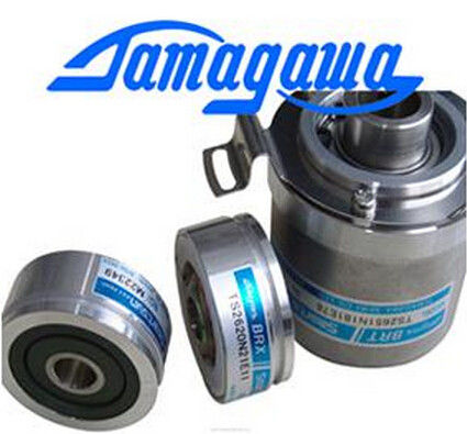
| Brand Name: | Tamagawa |
| Certification: | CE |
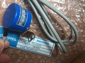
| Model Number: | TS5312N616-2000C-T |
| Minimum Order Quantity: | 1pcs |
|---|---|
| Packaging Details: | carton |
| Delivery Time: | in stock |
| Payment Terms: | T/T, Western Union, MoneyGram |
| Supply Ability: | 100pcs/week |
| TAMAGAWA: | TAMAGAWA | Temperature: | 20-80 |
|---|---|---|---|
| Color: | Black | Japan: | Japan |
| Material: | Iron | Wire: | Wire |
| Dimension: | 50mm | TS5312N616-2000C-T: | TS5312N616-2000C-T |
TS5312N616-2000C-T
TS3103N5037
TS4509N1002E200
TS3218
TS1508N202
TS3684N1E3
TS3653N13E7
TS3624N103E5
TS16N18E11
TS3501N
TS4509N1202E200
TS3218N42
TS1508N77
TS3684N2E6
TS3653N12E6
TS3624N203E5
TS2013N191E26
TS3510N39E10
TS4509N1831E200
TS3218N5
TS1508N85
TS3684N3E8
TS3653N2E5
TS3624N22E4
![]()
![]()
![]()
![]()
| operator controls or a recessed arrangement of operator | |
| controls. splashing and surging water suitable protective devices or installation in waterproof housings. |
|
| direct solar radiation suitable shading or installation in appropriately sheltered locations. |
mechanical damage suitable demarcation, protective devices, or installation in
rugged housings.EMC (electromagnetic compatibility) describes the capability of electrical apparatus
to operate without faults in a given electromagnetic environment, without being
affected by the environment and without affecting it in an unacceptable manner.
Introduction
Although the and its components were developed for operation in an
industrial environment and meet high EMC requirements, you should carry out
EMC planning before installing your control system, taking possible interference
sources into account and incorporating them in your observations.
Possible Effects of Interference
Electromagnetic interference can affect the programmable controller in different
ways:
• Electromagnetic fields which directly affect the system
• Interference picked up via bus signals (PROFIBUS DP, etc.)
• Interference acting via the process wiring
• Interference reaching the system via the power supply and/or protective ground
Figure A-1 shows the possible routes for electromagnetic interference.
Interference can reach the programmable controller via four different coupling
mechanisms, depending on the transmission medium (conducted or
non-conducted) and distance between interference source and the equipment.
Direct Coupling Direct or metallic coupling always
occurs when two circuits have a
common conductor.
• Switched devices (supply affected
by inverters and external power
supply units)
• Motors being started
• Different potentials of component
cases with a common power
supply
• Static discharges
Capacitive Coupling Capacitive or electrical coupling
occurs between conductors which are
at different potentials.
The degree of coupling is proportional
to the voltage variation as a function
of time.
• Interference pickup via parallel
signal cables
• Static discharge of the operator
• Contactors
Inductive Coupling Inductive or magnetic coupling occurs
between two conductor loops through
which current is flowing. Interference
voltages are induced by the magnetic
fluxes associated with the currents.
The degree of coupling is proportional
to the current variation as a function of
time.
• Transformers, motors, electric
welders
• Parallel AC supply cables
• Cables with switched currents
• Signal cables with a high
frequency
• Unconnected coils
Radiated Interference There is a radiation path when a