 |
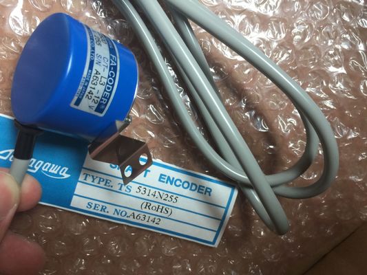
| Place of Origin: | Japan |
| Brand Name: | Tamagawa |
| Certification: | CE |
| Model Number: | TS5312N616 |
| Minimum Order Quantity: | 1pcs |
|---|---|
| Packaging Details: | carton |
| Delivery Time: | carton |
| Payment Terms: | T/T, Western Union, MoneyGram |
| Supply Ability: | 100pcs/week |
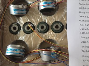
| TAMAGAWA: | TAMAGAWA | Material: | Iron |
|---|---|---|---|
| TS5312N616: | TS5312N616 | Temperature: | 20-80 |
| Wire: | Wire | Color: | Gray |
| Dimension: | 40mm |
TS3103N156
TS5312N616
TS2013N191E26
TS3510N39E10
TS4509N1831E200
TS3218N5
TS1508N85
TS3684N3E8
TS3653N2E5
TS3624N22E4
TS2014N181E32
TS3653N95E8
TS4509N2002E200
TS3250E12
TS1526N55
TS3692N103
TS3624N2E3
TS3624N23E5
TS2014N311E32
TS3617N2E7
TS4509N2405E200
TS3275N125
TS1562N102
TS3692N41
![]()
![]()
![]()
![]()
| conductor is subjected to an | Ensure proper routing of lines when wiring (see Sections A.7 and A.8). |
| electromagnetic wave. Impinging of | |
| the wave results in induced currents | Correct Cable Routing |
and voltages.
• Local transmitters (for example,
two-way radios)
• Spark gaps (spark plugs,
collectors of electric motors,
welders)In many cases, you can ensure electromagnetic compatibility by observing the
following five basic rules:
Rule 1: Large Area Grounding
When installing the programmable controllers, provide large-area good quality
grounding of the inactive metal parts (see Section A.3).
• Make a large-area low-impedance connection of all inactive metal parts to
chassis ground.
• For screw connections on painted or anodized metal parts, either use special
contact washers or remove the insulating protective layers from the contact
points.
• If possible, do not use aluminum parts for grounding. Aluminum oxidizes easily
and is therefore less suitable for grounding.
• Make a central connection between chassis ground and the ground/protective
ground conductor system.
Arrange the cabling in line groups (AC power cables, power supply cables,
signal lines, data lines).
• Always install AC power cables and signal or data lines in separate ducts or
bunches.
• Route the signal and data lines as closely as possible to grounded surfaces
such as cabinet elements, metal bars and cabinet panels.
Rule 3: Secure Cable Shields
Ensure that cable shields are properly secured (see Section 4.9).
• Only use shielded data lines. The shield must have a large-area connection to
ground at each end.
• Analog lines must always be shielded. For the transfer of signals with low
amplitudes, it may be advisable to connect the shield to ground at only one end.
• Provide the line shields with a large-area connection to a shield/protective
ground bar immediately after the cabinet inlet, and secure the shields with cable
clamps. Route the grounded shield as far as the module without interruption, but
do not ground it there again.
• There must be a low-impedance connection between shield/protective ground
bar and cabinet/housing.
• Use metal or metallized connector cases for shielded data lines.Employ special EMC measures for particular applications (see Section 4.11).
• Fit suppressors to all inductors which are not controlled by modules.
• Use incandescent bulbs or suppressed fluorescent lamps in the immediate
vicinity of your controller for illuminating cabinets or housings.