 |
| Place of Origin: | Japan |
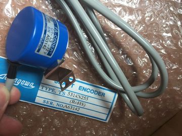
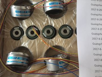
| Brand Name: | Tamagawa |
| Certification: | CE |
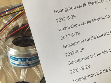
| Model Number: | TS5217N530 |
| Minimum Order Quantity: | 1pcs |
|---|---|
| Packaging Details: | carton |
| Delivery Time: | in stock |
| Payment Terms: | T/T, Western Union, MoneyGram |
| Supply Ability: | 100pcs/week |
| TAMAGAWA: | TAMAGAWA | Material: | Iron |
|---|---|---|---|
| Color: | Black | Temperature: | 20-80 |
| Wire: | Wire | Dimenision: | 50mm |
| TS5217N530: | TS5217N530 | Japan: | Japan |
![]()
![]()
![]()
![]()
| achieve attenuation of lower frequencies. Single-ended connection of the shield | Analog signals of a few mA or μA are transmitted |
| may be advantageous when | Foil shields (static shields) are used. |
| An equipotential bonding conductor cannot be laid | For data cables in serial communication, only use metallic or metallized |
TS3103N156
TS5217N530
TS3624N2E3
TS3624N23E5
TS2014N311E32
TS3617N2E7
TS4509N2405E200
TS3275N125
TS1562N102
TS3692N41
TS3653N13E9
TS2014N18E32
TS2014N312E32
TS3617N3E10
TS4509N7000E100
TS3153N15E18
TS1567N132
TS3692N42
TS3653N2E6
TS2014N43E31
TS2018N303E51
TS3617N3E8
TS4514N1021E200
TS3602N213E8
connectors. Secure the shield of the data cable to the connector housing. Do not
connect the shield to Pin 1 of the connector.
For stationary operation, you should strip the shielded cable without damaging the
shield and connect it to the shield/protective ground bar.
Note
In the event of potential differences between grounding points, a circulating current
may flow via the shield connected at both ends. In this case, install an additional
equipotential bonding conductor (see Section A.6Observe the following points with regard to the shield:
• Only use cable clamps made of metal to secure braided shields. The clamps
must surround the shield over a large area and provide good contact.
• Connect the shield to a shield bus immediately after entry of the cable into the
cabinet. Route the shield to the module but do not connect it there again to the
chassis ground or the shield bus.
• For installation other than in cabinets (for example, wall mounting), you can
provide contact between the cable shields and the cable duct.
Shown in the figure A-4 are some methods of securing shielded cables with cable
clamps.Potential differences can occur between separate system components, leading to
high transient currents; for example, if cable shields are fitted on both sides and
grounded at different system components.
Potential differences can be caused by different electrical supplies.
!
Caution
This can result in damage.
Cable shields are not suitable for equipotential bonding.
Use the prescribed cables exclusively (e.g. those with a 16 mm2 cross-section).
Ensure also that the cable cross-section is adequate when installing MPI/DP
networks, since otherwise the interface hardware may be damaged or even
destroyedYou must reduce the potential differences by laying equipotential bonding
conductors to ensure that the electronic components used function correctly.
Observe the following points for installing an equipotential bonding conductor:
• The lower the impedance of the equipotential bonding conductor, the higher the
efficiency of the equipotential bonding.
Where two sections of an installation are interconnected via shielded signal
lines whose shields are connected to the ground/protective conductor at both
ends, the impedance of the additional equipotential bonding conductor must not
exceed 10% of the shield impedance.
• The cross-section of an equipotential bonding conductor must be rated for the
maximum circulating current. In practice, equipotential bonding conductors with
a cross-section of 16 mm2 have proved to be effective.
• Use equipotential bonding conductors made of copper or zinc-plated steel.
Provide a large-area contact between the cables and the ground/protective
conductor and protect them from corrosion.
• Lay the equipotential bonding conductor in such a way that the surface between
the conductor and the signal lines is as small as possible. (see Figure A-5)Inside buildings, clearances must be observed between groups of different cables
to achieve the necessary electromagnetic compatibility (EMC). Table A-2 provides
you with information on the general rules governing clearances to enable you to
choose the right cables.
How to Read the Table