|
| Place of Origin: | Japan |
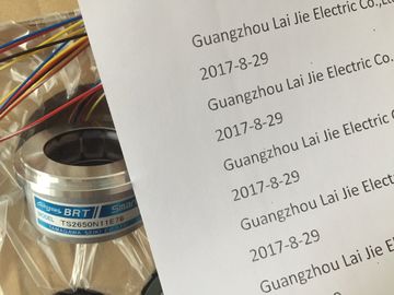
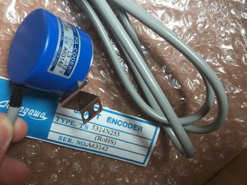
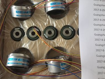
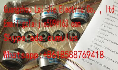
| Brand Name: | Tamagawa |
| Certification: | CE |
| Model Number: | TS5233N430 |
| Minimum Order Quantity: | 1pcs |
|---|---|
| Packaging Details: | carton |
| Delivery Time: | in stock |
| Payment Terms: | T/T, Western Union, MoneyGram |
| Supply Ability: | 100pcs/week |
| Tamagawa: | Tamagawa | TS5233N430: | TS5233N430 |
|---|---|---|---|
| Japan: | Japan | Material: | Iron |
| Temperature: | 20-80 | Color: | Black |
| Dimension: | 60mm |
| Rule 5: Standard Reference Potential | |
| Create a standard reference potential; ground all electrical apparatus if possible (see Sections 4.10 and 4.12). |
|
| Install equipotential bonding conductors of sufficient rating when potential differences exist or are expected between sections of your system. |
TS3103N156
TS5233N430
TS3617N1E1
TS1922N3
TS4603N2002E200
TS2097N1E9
TS2151N1E26
TS3617N3E9
TS4514N2405E200
TS3617N1E2
TS2014N181E32
TS4603N7002E200
TS4602N6321E100
TS3617N2E4
TS3617N13E9
TS4515N1202E200
TS3617N11E1
TS2014N182E32
TS1505N55
TS4515N6000E200
TS4603N1000E100
TS3617N2E5
TS3617N40E3
TS4515N2405E200
Use specific grounding measures. Grounding the control system is a protective
and functional measure.
• Connect the system sections and cabinets containing central racks and
expansion racks to the grounding/protective ground system in a star
configuration. This prevents the formation of ground loops.
See also
Cable shielding, page A-13
Cabling outside buildings, page A-19
Cabling inside buildings, page A-17
Mounting of programmable controllers for EMC, page A-9Measures for suppressing interference are often only applied when the control
system is already operational, and the proper reception of a useful signal is found
to be impaired.
The cause of such interference is often due to insufficient reference potentials
which can be attributed to errors during assembly. This section tells you how to
avoid such errors.
Inactive Metal Parts
Inactive parts are all the conductive parts which are electrically isolated from active
parts by basic insulation, and can only develop a potential in the event of a fault.
Grounding of Inactive Metal Parts During Installation
When installing the , ensure large-area grounding of all inactive metal parts.
Properly implemented chassis grounding creates a standard reference potential for
the control system, and reduces the effects of picked-up interference.
The chassis ground provides the electrical interconnection between all inactive
parts. The entirety of all interconnected inactive parts is known as the chassis
ground.
Even in the event of a fault, the chassis ground must not develop a dangerous
touch potential. It must therefore be connected to the protective ground conductor
via an adequate conductor cross-section. To prevent ground loops, locally
separated ground elements such as cabinets, structural and machine parts must
always be connected to the protective ground system in star configuration.
Ensure the following when chassis grounding:
• Connect the inactive metal parts with the same degree of care as the active
parts.
• Ensure low-impedance connections between metal parts, for example, with
large-area good quality contact.
• With painted or anodized metal parts, the insulating protective layer must be
penetrated or removed at the contact point. Use special contact washers or
scratch the layer off fully at the contact point.
• Protect the connection points from corrosion, for example, with suitable grease.
• Use flexible grounding strips to connect movable grounded parts such as
cabinet doors. The grounding strips should be short and have a large surface,
because the surface is decisive in providing a path to ground for high-frequency
interference.Below you will find two examples of configurations for programmable controllers for
EMC.
Example 1: Cabinet Configuration for EMC
Figure A-2 shows a cabinet installation in which the measures described above
(grounding of inactive metal parts and connection of cable shields) have been
applied. However, this example only applies to grounded operation. Observe the
points marked in the figure when installing your system.The numbers in the following list refer to the numbers in Figure A-2.
Table A-1 Key for Example 1Grounding strips If there are no large-area metal-to-metal
connections, you must interconnectinactive metal
parts such as cabinet doors or support plates via
grounding strips or to ground. Use short grounding
strips with a large surface.
2 Supporting bars Connect the supporting bars and the cabinet
housing over a large area (metal-to-metal
connection).
3 Secure the rack There must be a large-area metal-to-metal
connection between supporting barand rack.
4 Signal lines Use cable clamps on the protective ground bar or an
additional shield bus forlarge-area connection of the
shield of signal lines.
5 Cable clamp The cable clamp must surround the braided shield
over a large area and ensuregood quality contact.
6 Shielding bus Provide a large-area connection between the shield
bus and supporting bars (metal-to-metal
connection). The cable shields are connected to the
shield bus.
7 Protective ground
bar
Provide a large-area connection between the protective
ground bar and supporting bars (metal-to-metal
connection). Connect the protective ground bar to
the protective conductor system via a separate conductor
(minimum cross-section 10 mm2).
8 Conductor to the
protective conductor
system (grounding
point)
Provide a large-area connection between the
conductor and the protective conductor system
(grounding point).
Example 2: EMC--compliant Wall Mounting
If you operate your in a low-interference environment in which the
permissible ambient conditions are complied with (see the Module Data reference
manual, Chapter 1), you can mount your in frames or on the wall.
Picked-up interference must be given a path to large metal surfaces. You should
therefore secure standard mounting channels, shield, and protective ground bars to
metal structural elements. For wall mounting in particular, installation on reference
potential surfaces made of sheet steel has proved advantageous.
Provide a shield bus for connecting the cable shields if you install shielded cables.
The shield bus can simultaneously serve as the protective ground bar.Use special contact washers with painted and anodized metal parts, or remove
the insulating protective layers.
• Provide large-area, low-impedance metal-to-metal connections when securing
the shield/protective ground bar.
• Cover the AC supply conductors in a shockproof arrangement.
Figure A-3 shows an example of wall mounting for EMCA cable is shielded to attenuate the effects of magnetic, electrical, and
electromagnetic interference on this cable.
Principle of Operation
Interference currents on cable shields are discharged to ground via the shield bus
which is electrically connected to the housing. To prevent these interference
currents themselves from becoming an interference source, a low-impedance
connection to the protective ground conductor is particularly important.
Suitable Cables
If possible, only use cables with a braided shield. The coverage density of the
shield should be at least 80%. Avoid cables with a foil shield because the foil can
be easily damaged by tensile and compressive stress at the securing points; this
can reduce the shielding effect.
Grounding the Cable Shields
Generally, you should always connect both ends of the shield to the chassis ground
(that is, at the beginning and end of the cable). Grounding the shields at both ends
is essential to achieve a good degA-19A-19A-19A-19ree of suppression of
interference in the higher frequency region.
In exceptional cases, you can connect only one end of the shield to the chassis
ground (for example, at the beginning or end of the cable). However, you only