 |
| Place of Origin: | Japan |
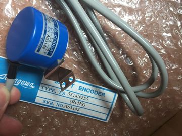
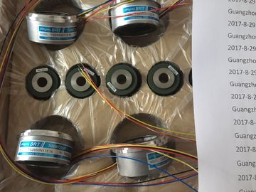
| Brand Name: | Tamagawa |
| Certification: | CE |
| Model Number: | TS2650N1E78 |
| Minimum Order Quantity: | 1pcs |
|---|---|
| Packaging Details: | carton |
| Delivery Time: | in stock |
| Payment Terms: | T/T, Western Union, MoneyGram |
| Supply Ability: | 100pcs/week |
| Tamagawa: | Tamagawa | TS2650N1E78: | TS2650N1E78 |
|---|---|---|---|
| Material: | Iron | Color: | Black |
| Temperature: | 30-80 | Wire: | Wire |
| Dimension: | 40mm |
| The munication bus is continuous (global), | The two CPUs in a segmented CR may be in different operating states. |
| whilst the I/O bus is divided into two I/O bus segments of 10 and 8 slots respectively |
The two CPUs can municate with each other via the munication bus. |
| One CPU can be inserted per local bus segment. | All the modules inserted in a segmented CR are powered by the power supply module at slot 1 |
TS3103N156
TS2650N1E78
TS2025N471E69
TS3630N102E4
TS5017N60
TS5007N122
TS4502N1000E200
TS1983N146E5
TS3653N78E5
TS2014N181E32
TS3630N22E3
TS5108-N153-5V
TS5007N635
TS4502N1202E200
TS252N30E1
AU6270N103E63
TS3653N94E5
TS5208N141E78
TS3630N22E4
TS5146N10
TS5208N500
TS4502N2000E100
TS3503N11E43
TS3653N181E8
Both segments have a mon backup battery.
The following figure shows a segmented CR with divided I/O bus and continuous
munication bus.ristics
The “subdivided” characteristic relates to the configuration of the CR. In the
(non-divided) CR the I/O bus and munication bus are continuous and
interconnect all the slots; in the subdivided CR, however, the I/O bus and
munication bus consist of two segments each. The UR2-H rack used here
functions as two electrically isolated UR2 racks on the same rack profile.
A subdivided CR has the following important characteristics:
• The munication bus and I/O bus are subdivided into two segments with 9
slots each.
• Each segment represents a self-contained CR.
The following figure shows a divided CR with a divided I/O bus and munication
bus.The racks are designed for wall mounting, mounting on rails, and for
installation in frames and cabinets. Their mounting dimensions are pliant with
DIN 41 494.
According to the UL/CSA and the EU Directive 73/23/EEC (low-voltage directive),
installation in a cabinet, a casing, or a closed operations room is necessary in order
to fulfil the requirements for electrical safety (see Reference Manual, Chapter 1).
You must observe the minimum distances between the rack and neighboring
devices. You need these minimum clearances during installation and operation.
• For fitting and removing modules
• For fitting and disconnecting the module front connectors
• To ensure the air flow required for cooling the modules during operation
The following figure shows the minimum space you must provide for a rack.
A cable duct or fan subassembly must be installed in the 19-inch pitch immediately
below the rack. Additional space for cable routing must be provided on both sides.
The following figure shows how much space you need to allow for when using a
cable duct or fan subassemblyThe following figure shows the dimensions for racks with 18, 9 and 4 slots and the
positions of cutouts for screw mounting.
The cutouts are arranged according to the 19-inch standard.
Screw the rack onto the mounting panel.
When mounting the equipment on a metal mounting plate, make sure to establish a
low-impedance connection. On varnished or anodized metals, for example, wlayws
use a suitable contact agent or special contact washers.
Special measures need not be taken if you do not use this type of panel.
Connect the rack to the chassis ground. A threaded bolt is provided for this
purpose on the bottom left of the rack.
Minimum cross-section of the conductor to the chassis ground: 10 mm2.
If the is mounted on a mobile rack, you must provide a flexible conductor to
the chassis ground.
Note
Always ensure that there is a low-impedance connection to the chassis ground
(see the figure below). You achieve this with the shortest possible, low-resistance
conductor with a large surface to establish large-area contact.
For assemblies containing two or more racks, make allowances for
additional clearance between the racks for installing a fan subassembly or cable
duct.
The figure below shows the clearance you must allow between two racks of the
during installation.The figure below shows how much space you must allow for when assembling an
from two racks with a cable duct or fan subassembly. This requirement is
increased by a height of 400 mm for each additional rack with a cable duct or fan
subassemblyA minimum clearance as shown in the above figure between rack and cable duct
or fan subassembly must not be provided, but is essential between two adjacent
racks and between racks and other equipme
The racks offer the option of connecting the 24-V load voltage ground in the
non-isolated configuration to the 5-V ground (reference potential M, logic ground).
Connect the chassis ground to the reference point for non-isolated modules. The
reference point is metallically connected to the reference potential M.
The following figure shows the position of the reference point on a rack.
For the connection to the reference point, use a cable lug for M4, a suitable spring
lock washer (for example, clamping washer to DIN 6796) and the cylinder-head
screw supplied.
Ungrounded assembly: Undo the fixing screws of the metallic connection on the
rack. Tilt the connection downwards. For the connection to the reference point, use
the original M4 x 8 supplied. Use the tilted metallic connection as a washer.