|
| Place of Origin: | Japan |
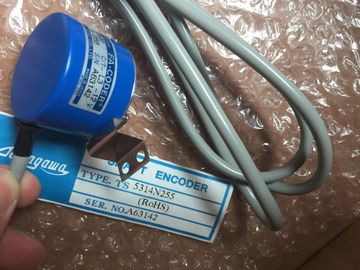
| Brand Name: | Tamagawa |
| Certification: | CE |
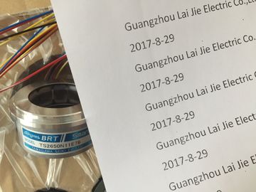
| Model Number: | TS5013N89 |
| Minimum Order Quantity: | 1pcs |
|---|---|
| Packaging Details: | carton |
| Delivery Time: | in stock |
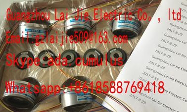
| Payment Terms: | T/T, Western Union, MoneyGram |
| Supply Ability: | 100pcs/week |
| TAMAGAWA: | TAMAGAWA | TS5013N89: | TS5013N89 |
|---|---|---|---|
| Material: | Iron | Color: | Black |
| Temperature: | 20-80 | Wire: | Wire |
| Japan: | Japan | Dimension: | 50mm |
| Grounded assembly: Leave the metallic connection on the rack. For the connection to the reference point, use the original M4 x 8.Do |
the reference point and the rack profile behind it and therefore the connection for the chassis ground. |
| not use any cylinder-head screws that are longer than 6 mm for the connection | For this reason as well, leave the metallic connection on the rack and use it as a washer in an ungrounded configuration. |
| to the reference point. Otherwise, you may create an undesired connection between | Under extreme ambient conditions, particularly when operating modules in |
TS3103N156
TS5013N89
TS5013N64
TS5016N61
TS5013N66
TS5016N63
TS5016N64
TS5017N60
TS5019N60
TS5420N60
TS5778N155
TS5013N68
TS5013N69
TS5208N131
TS5208N23
TS2025N471E69
TS2014N181E32
TS5208N111E78
TS5208N141E78
TS5631N224
cabinets, you can use the cable duct or fan subassembly to optimize ventilation.
There are two methods of supplying air to the modules. You draw in air either from
the back or from below. The cable duct and fan subassembly can be converted for
this purpose.
The following figure shows the ventilation when air is drawn in from the back.The following figure shows the ventilation when air is drawn in from the bottom.At the base of the cable duct and the fan subassembly, there is a cover that you
can move in order to modify the air duct. To do this, proceed as follows:
1. Using a screwdriver, make a quarter turn counter-clockwise to open the two
quick-release locks at the front of the cable duct or fan subassembly.
2. Grasp the base with both hands; press it gently downward and pull it fully out of
the cable duct or fan subassembly.
3. The base cover is secured with clips. Firmly press down the cover in the clip
areas to remove it.
4. Snap the cover into the snap-in hinges at the rear edge of the base, rougly at a
right angles to the base.
5. Slide the base in again and push it up.
6. Use a screwdriver to make a quarter turn clockwise and close the two
quick-release locks.
The following figure shows both methods of selecting the ventilation by
appropriately fitting the cover in the base of the cable duct or fan subassembly
The cover is fitted in the base of the cable duct or fan subassembly. Air is supplied
from the back.
Filter Mat (Optional)
To filter the air supply, you can fit a filter mat for the cable duct and fan
subassembly. The filter mat is optional and is not part of the cable duct or fan
subassembly.
Like the cover, the filter mat can be inserted flat in the base or at its rear edge in
the corresponding snap hinges or quick-release locks.1. Remove the left cover from the fan subassembly.
Using a 17 mm open-ended wrench, slacken the quick-release lock a quarter
turn.
Pull out the left cover of the fan subassembly. To do this, move the left cover
parallel to the fan subassembly in order to avoid damaging the plug-in contact
on the other side.
he following figure shows you how to remove the left cover.
Provide the fan subassembly with dummy plates beneath free slots, this will
ensure optimum ventilation.
The fan subassembly is supplied with 18 dummy plates, arranged as 2 units, each
with 9 individual dummy plates. By breaking at one of the rupture joints, you can
split up the individual plates as required.
2. Remove the dummy plates which are not required by slackening the snap-in
mechanisms of the covers and pulling them off.
3. Break off as many dummy plates as required.
. Attach the dummy plates to the free slots:
-- Place the dummy plates on the rear wall of the cable routing,
-- Push the dummy plates back so that the noses of the dummy plates will fit
into the cutouts provided,