|
| Place of Origin: | Japan |
| Brand Name: | Tamagawa |
| Certification: | CE |
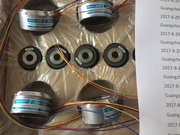
| Model Number: | TS2651N181E78 |
| Minimum Order Quantity: | 1pcs |
|---|---|
| Packaging Details: | carton |
| Delivery Time: | in stock |
| Payment Terms: | T/T, Western Union, MoneyGram |
| Supply Ability: | 100pcs/week |
| TAMAGAWA: | TAMAGAWA | Material: | Iron |
|---|---|---|---|
| Japan: | Japan | TS2651N181E78: | TS2651N181E78 |
| Color: | Black | Wire: | Wire |
| Temperature: | 20-80 |
| Check whether the voltage selector switch in the fan subassembly is set to your line voltage (see Figure 4-24). |
A 160 mA slow blow fuse for the 230 V range. |
| The fan subassembly has two standard fuses: | A 160 mA slow blow fuse for the 230 V range. |
| A 250 mA slow blow fuse for the 120 V range | If you change the voltage range, |
TS3103N156
TS2651N181E78
TS5208N131
TS5208N23
TS2025N471E69
TS2014N181E32
TS5208N111E78
TS5208N141E78
TS5631N224
PULSE
GENERATOR
RP-182
750PPR
PULSE
GENERATOR
RP-182
1500PPR
PULSE
GENERATORRP-482E,750PPR
Strip the cables of the power cable. Press-fit wire end ferrules onto the
conductors.
2. Insert the wires in the power terminals of the fan subassembly. Use a suitable
screwdriver to release the spring contacts of the power terminals.
3. The small cover serves as a strain relief for the power cable. Choose one of the
three sizes provided to suit your cable cross-section.
4. Screw the strain relief on
Depending on the number of cables and plug-in lines merging at the particular
rack, the cross-section of the cable duct or fan subassembly may not be sufficient
to accept all cables.
You should therefore route half the cables toward each side via the cable duct or
fan subassembly.
Securing Cables
There are eyes for securing cables on both sides of the cable duct or fan
subassembly (see Reference Manual Module Specifications, Chapter 6). You can
secure the cables to these eyes with cable ties, for example.
Shield Contact
The cable duct and fan subassembly offer the facility of electrical contact for cable
shields. You can use the shield clamps provided
(see Reference Manual Module Specifications, Chapter 9).
To establish contact for the cable shields, strip the outer insulation in the region of
the shield clamp, and trap the cable shield under the shield clamp.
4.23 Routing Fiber-Optic Cables
Cable Routing
Indoor fiber-optic cables (for example, for connecting synchronization submodules)
are permitted for use in buildings, cable ducts, and channel trunking.
The maximum strain load when assembling is 1000 N and during operation 150 N.Minimum bending radius of the cables:
• At the connector: 55 mm
• Otherwise: 30 mmYou can connect an device to various subnets:
• Via Simatic Net CP Ethernet to an Industrial Ethernet subnet
• Via Simatic Net CP PROFIBUS to a PROFIBUS-DP subnet
• Via the integrated MPI interface to an MPI subnet
• Via the integrated PROFIBUS-DP interface to a PROFIBUS DP subnet
Same Configuration
e recommend you use the same bus components as for a PROFIBUS DP
network configuration when configuring an MPI network. The same configuration
rules apply
This interface of the CPU uses a Simatic S7-specific protocol for the
communication with programming devices (by means of STEP 7), operator panels,
and other S7 CPUs. The bus structure corresponds to PROFIBUS.
Configuring Communication
In order that the individual nodes of an MPI or PROFIBUS-DP network can
communicate with each other, you must assign MPI or PROFIBUS-DP addresses
to them. The Manual Configuring Hardware and Communication Connections
STEP 7 describes how to assign these addresses and what you must take into
account.