 |
| Place of Origin: | Japan |
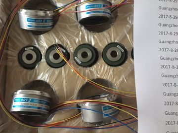
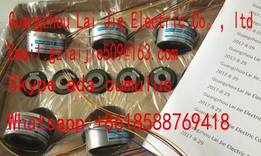
| Brand Name: | Tamagawa |
| Certification: | CE |
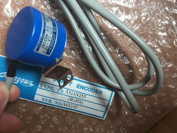
| Model Number: | TS5013N64 |
| Minimum Order Quantity: | 1pcs |
|---|---|
| Packaging Details: | carton |
| Delivery Time: | in stock |
| Payment Terms: | T/T, Western Union, MoneyGram |
| Supply Ability: | 100pcs/week |
| TAMAGAWA: | TAMAGAWA | TS5013N64: | TS5013N64 |
|---|---|---|---|
| COLOR: | BLACK | Temperature: | 20-80 |
| Material: | Iron | Japan: | Japan |
| Wire: | Wire |
| Method 2: Using the “S7-SmartLabel” Add-On Tool for SIMATIC STEP 7 | |
| ou can derive the labeling directly from the STEP 7 project. The basis for | |
| application-specific labeling is the symbol table in STEP 7 |
TS3103N156
TS5013N64
TS3684N13E8
TS3617N1E3
TS3617N1E1
TS3617N1E2
TS3617N2E4
TS3630N11E1
TS3664N2E4
TS3653N13E7
TS3653N12E6
TS3653N2E5
TS3624N2E3
TS3653N13E9
TS3653N2E6
TS3653N3E7
TS3653N3E8
TS3653N3E9
TS1980N43E12
TS1980N56E12
Detailed information is
available on the Internet under:
To reduce the risk of a wired front connector being plugged into the wrong type of
module after rewiring or module replacement, the signal modules have a coding
key for front connectors.
A coding key comprises two parts: one part is permanently connected to the
module; the second part is still connected to the first part when delivered
(see Figure 4-20).
When you plug in a front connector, the second part of the coding key engages in
the connector, becoming detached from the part connected to the signal module.
Both parts of the coding key are mating elements and a front connector with the
wrong mating element cannot be plugged into this signal module.
Front Connector Coding on the Signal Modules
Shown in the following table is the allocation between the different front connector
coding keys and individual signal modules.
Table 4-4 Front connector coding elements
You can only plug in the connector when the power supply module is installed
(lower mounting screw tightened).
! Caution
Modules can be damaged.
If, for example, you plug the front connector of a digital input module into a digital
output module, the module can be damaged. If, for example, you plug the front
connector of an analog input module into an analog output module, the module
can be damaged.
When plugging in the front connector, ensure that the module and front connector
are matched.
To plug in the front connector, follow the steps outlined below:
1. Hold the front connector horizontally and engage the front connector with the
coding key. After an audible click, the front connector will engage with the mount
and can be swung upwards.
2. Swing the front connector upwards. The two parts of the coding key will then be
separated.
3. Screw the front connector on.ecting the Interface Modules
When you assemble an automation system comprising a CR and one or more ERs,
you connect the racks via the connecting cables of the interface modules.
To interconnect the interface modules:
1. Ensure that all the connecting cables needed for the programmable controller
are ready. Allow for the maximum cable lengths permitted for your assembly
(see Chapter 2) and check that you have the correct cables
(see Reference Manual Module Specifications, Chapter 6).
2. Start with the send IM (the interface module in the central rack).
3. Open the cover of the send IM.
4. Plug the male connector of the first connecting cable into one of the female
connectors of the send IM and screw-tighten it.5. If you wish to interconnect two ERs segments to this send IM, plug the
connector of the second connecting cable into the second port of the send IM.
6. Close the cover of the send IM.Open the cover of the first receive IM (interface module in the ER).
8. Plug the free end of the connecting cable into the upper male connector
(receive interface) of the receive IM and screw the connector on.
9. Connect the remaining receive IMs by connecting one send interface (lower
female connector X2) to one receive interface (upper male connector X1) in
each case.