 |
| Place of Origin: | Japan |
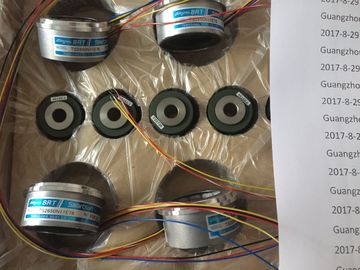
| Brand Name: | Tamagawa |
| Certification: | CE |
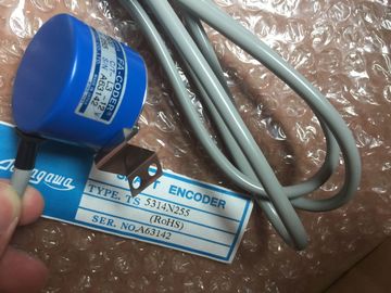
| Model Number: | TS5000N532 |
| Minimum Order Quantity: | 1pcs |
|---|---|
| Packaging Details: | carton |
| Delivery Time: | in stock |
| Payment Terms: | T/T, Western Union, MoneyGram |
| Supply Ability: | 100pcs/week |
| TAMAGAWA: | TAMAGAWA | Temperature: | 20-80 |
|---|---|---|---|
| Color: | Black | Material: | Iron |
| Japan: | Japan | Wire: | Wire |
| Dimension: | 40mm | TS5000N532: | TS5000N532 |
![]()
![]()
![]()
![]()
| Each signal module is provided with three labels | To label a front connector, follow the steps outlined below: |
| two blank labels and one printed label showing the terminal diagram for inputs and outputs. |
1. Enter the addresses of the individual channels on the two labels. |
| Figure 4-18 shows the locations for fitting the individual labels on the front connector. |
1. Enter the addresses of the individual channels on the two labels. |
TS3103N156
TS5000N532
TS3132N32
TS3134N21
TS3134N22
TS3134N317
TS3134N52
TS3166
TS3166N43
TS3212N32
TS3214N12
TS3214N13
TS3214N15
TS3214N16
TS3214N44
TS3218
TS3218N42
TS3218N5
TS3250E12
TS3275N125
TS3153N15E18
Each signal module is provided with three labels: two blank labels and one printed
label showing the terminal diagram for inputs and outputs.
Figure 4-18 shows the locations for fitting the individual labels on the front
connector.
To label a front connector, follow the steps outlined below:
1. Enter the addresses of the individual channels on the two labels. Note the slot
numbers on the labels to record the assignment of front connector to module.
2. Place a label on the left of the opened front connector. The label has a
T-shaped blank in the middle with which you can fix the label onto the front
connector housing. Bend the blank slightly to one side and push it behind the
corresponding cutout of the front connector whilst sliding in the label
(see Figure 4-19).
3. Refit the cover on the front connector.
4. Slide the label with the terminal diagram of the inputs or outputs into the interior
of the cover of the front connector.
5. Slide a label externally into the cover of the front connector.Print labels are prerequisite for professional, convenient labeling of your
SIMATIC signal modules, including FMs modules.
• The perforated labeling strips are available on DIN A4 sheets and can be easily
separated without the use of a tool. This makes them easy to use and ensures a
clean cut.
• The single-color labels are tear-proof and dirt-resistant. They are available in
petrol, light beige, red, and yellow.
SIMATIC I/O modules can be easily labeled application-specifically by
machine using a standard laser printer in one of the following two ways:
-- Use the print templates you can download free of charge from the Internet
-- Use the “S7-SmartLabel” add-on tool for SIMATIC STSIMATIC , 10 A4 label sheets, 4 labeling strips /
sheets for signal modules. Material: film, perforated, for laser
printers. 10 sheets per package.
6ES7492-2AX00-0AA0 Petrol
6ES7492-2BX00-0AA0 Light--beige
6ES7492-2CX00-0AA0 Yellow
6ES7492-2DX00-0AA0 RedMethod 1: Using Templates
1. Find the templates on the Internet
You can download the templates from the Internet free of charge. Search for the
templates on the Customer Supports homepage under article ID 11765788.
2. Download
The download contains templates for the labeling of modules.
The templates for make the labeling strips available for the outside of
the front connector cover and the terminal diagrams for the inside of the front
connector cover.
3. How to Print the Labeling Sheets Using the Templates
The idea is to use the templates to print directly onto the foil sheets. You can
use a laser printer to label the foil sheets. Proceed as follows:
a) Select page layout view in WORD to edit the template forms.
b) Label the module by clicking in the text boxes and entering the
application-specific designation.
c) Always print a preview of the form on white paper, and compare the layout
with the original labeling sheets. Because there are differences between the
different printers and printer drivers and their accuracy, the dimensions may
vary and adjustment may be necessary. If the line and column spacing is not
set correctly, you can adjust the position of the entire template under
“Header>Graphics>Position” and “File>Page Setup>Margins”.
d) When some templates are printed, a message reporting that the margins are
outside of the printable area appears. This message can be ignored.
e) Once you have printed the film sheets, make sure that you fold the labeling
strips along the perforation before separating them. This will ensure that the
edges of the strips are even. You can then apply the labeling strips to the
corresponding module.