 |
| Place of Origin: | Japan |
| Brand Name: | Tamagawa |
| Certification: | CE |
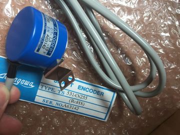
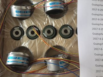
| Model Number: | TS5003N632 |
| Minimum Order Quantity: | 1pcs |
|---|---|
| Packaging Details: | carton |
| Delivery Time: | in stock |
| Payment Terms: | T/T, Western Union, MoneyGram |
| Supply Ability: | 100pcs/week |
| TAMAGAWA: | TAMAGAWA | Material: | Iron |
|---|---|---|---|
| Color: | Black | Temperature: | 20-80 |
| Wire: | Wire | TS5003N632: | TS5003N632 |
| Dimension: | 50mm | Japan: | Japan |
TS3103N156
TS5003N632
TS2014N311E32
TS2014N312E32
TS2018N303E51
TS20E12
TS20N2E11
TS2142N1E63
TS2151N1E26
TS2151N1E45
TS2151N11E45
TS2640N321E64
TS2641N31E64
TS2650N1E78
TS2650N11E78
TS2650N101E78
TS2651N111E78
TS2651N181E78
TS5000N532
TS5000N632
TS5003N632
TS5005N122
TS5007N122
TS5007N635
![]()
![]()
![]()
![]()
| Assign a logical address to the geographical address under STEP 7 | |
| Thislogical address is used for addressing the channel in the user program. Note |
|
| If your prises only a CR without ER, you can also use default addressing.Addressing |
Under certain conditions, the CPU can handle the assignment between logical
address and geographical address for you (default addressing). The logical
addresses are then permanently assigned to the slots (default address). Distributed
I/Os are not taken into account.
Conditions for Default Addressing
The CPU assigns default addresses under the following conditions:
• No multiputing
• If only signal modules are inserted
(no IM, CP, FM inserted; no expansion racks connected)
• If signal modules are used with their default settings (measuring ranges,
interrupt processing, etc.)
• If modules are inserted in STOP mode or during power off
(modules inserted while the system is in RUN or during a RUN → STOP →
RUN transition will be ignored)You determine the default address of a module from the number of the slot of the
module in the CR.
The algorithms used to calculate the default address are different for analog and
digital modules.
The following figure shows the numbering of slots in an 18-slot rack. You can also
read off the slot numbers directly from the rack.On the , the default addresses for digital modules start from 0 (First slot in
the central rack which is usually occupied by the power supply module) up to 68
(18th slot).
The algorithm used to calculate the default address of a digital module is:Default address = (slot number - 1) x 4Example
The default address of a digital module in the 12th slot is as follows:Default address = (12 - 1) x 4 = 44On the , the default addresses for analog modules start from 512 (first slotin the central rack which is usually occupied by the power supply module) up to1600.The algorithm used to calculate the default address of an analog module is:Default address = (slot number - 1) x 64 + 512ExampleThe default address of an analog module in the 6th slot is as follows:
Default address = (6 - 1) x 64 + 512 = 832A channel on a digital module is addressed bit-wise. For a digital input module with
32 inputs, four bytes (starting with the default address of the module) are used to
address the inputs, and for a digital input module with 16 inputs, two bytes are
used. Bits 0 to 7 in these bytes are then reserved by the individual inputs (from top
to bottom).
This is clarified by the following figure with the example of a digital input modulewith 32 channels at slot 12 (default address 44). With a digital output module, thefirst character is a Q instead of an I.Channels on analog modules are addressed word-wise.Starting with the default address of the module, which also represents the address
of the uppermost channel of the module, the addresses of the individual channels(from top to bottom) increase by two bytes (= one word).This is clarified by the following figure with the example of a digital input module
with 8 channels at slot 6 (default address 832). With an analog input module, thefirst characters are IW instead of QW.The modules of the system are supplied with all the requiredoperating
voltages by a power supply module, via the backplane bus of the rack. Whichpower supply module you use in a rack depends on your system requirements (linevoltage, current consumption of the modules used).You must provide load voltages and currents via external load current power
supplies.The following figure shows how the individual modules of the are suppliedwith current and voltage.The power supply modules must not be connected in parallel on their secondarysides.You should make an estimate of the power requirement for each rack of your
system in order to select the appropriate power supply module for the rack.Current consumption and power dissipation of the individual modules can be foundin the relevant data sheets.
Calculation ExampleThe following modules are to be fitted in a CR with 18 slots:• 1 CPU 414-1• 3 analog input modules SM 431;AI 16 x 16 bits
• 5 digital input modules SM 421;DI 32 x 24 VDC
• 6 digital input modules SM 422;DO 32 x 24 VDC/0.5A 1 send IM, IM 460-0