 |
| Place of Origin: | Japan |
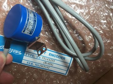
| Brand Name: | Tamagawa |
| Certification: | CE |
| Model Number: | TS5005N122 |
| Minimum Order Quantity: | 1pcs |
|---|---|
| Packaging Details: | carton |
| Delivery Time: | in stock |
| Payment Terms: | T/T, Western Union, MoneyGram |
| Supply Ability: | 100pcs/week |
| TAMAGAWA: | TAMAGAWA | TS5005N122: | TS5005N122 |
|---|---|---|---|
| Material: | Iron | Temperature: | 20-70 |
| Japan: | Japan | Color: | Black |
| Wire: | Wire |
TS3103N156
TS5005N122?
TS3624N2E4
TS3624N3E5
TS3624N3E6
TS3630N1E1
TS3630N1E2
TS3630N2E3
TS3630N2E4
TS3630N3E5
TS3630N3E6
TS3630N1303E9
TS3630N1306
TS3630N11E1
TS3630N11E2
TS3630N12E3
TS3630N12E4
TS3630N13E5
TS3630N13E6
FA-CODER
TS5214N566
TS5205N450
TS5205N454
TS5205
N450
![]()
![]()
![]()
![]() Single-pole
Single-pole
| Isolating switches | Single-pole |
| Short-circuit and overload protection: | protection of circuits |
| in groups for sensors and actuators | grounded secondary |
circuit:
single-pole
protection
• Otherwise:
all-pole
protection
Load current PS for AC power circuits
with more than five items of
electromagnetic apparatus
¢ Isolation by
transformer is
remended
Isolation by
transformer is
requiredLoad current circuits must be grounded.
Reliable functional safety is provided by the mon reference potential (ground).
Provide a detachable connection to the protective ground conductor at the load
current power supply (Terminal L- or M) or on the isolating transformer
(Figure 4-1, £). In the event of faults in the power distribution, this will facilitate the
locating of ground faults.Shown in Figure 4-1 is the position of the in the overall installation (load
current power supply and grounding concept) with supply from a TN-S system.
Note: The arrangement of supply terminals shown is not the actual arrangement; it
has been chosen for reasons of clarity.You use an with grounded reference potential in machines or industrial
plants.
Discharge of Interference Currents
When the is configured with a grounded reference potential, any
interference currents are discharged to the chassis ground.
Terminal Connection Model
When delivered, the racks have a detachable metallic connection between the
internal reference potential M of the modules and the frame element of the racks.
Situated behind this connection is an RC network which is placed in the circuit for
the ungrounded configuration. This connection is located at the left edge of the
rack. The terminal for the chassis ground also has an electrical connection to the
frame element.
Shown in Figure 4-2 is an configured with grounded reference potential. To
ground the reference potential M, you must connect the chassis ground terminal to
the chassis ground and you must not remove the jumper between reference
potential M and the frame element terminal on the rack.In large installations, it may be necessary to configure the with an
ungrounded reference potential, for example, for ground fault monitoring. This ishe case in the chemical industry or in power plants, for example.
Discharge of Interference CurrentsWith the in an ungrounded configuration, any interference currents are
discharged to the chassis ground via an RC network integrated in the rack.Terminal Connection Model
Shown in Figure 4-3 is an configured with ungrounded reference potential.In this case you must remove the jumper between reference potential M and theframe element terminal on the rack. The reference potential M of the isthen connected via the RC network to the chassis ground terminal. When you
connect this terminal to the chassis ground, RF interference currents will bedischarged and static charges will be avoided.When using power supply units, ensure that the secondarywinding is notconnected to the protective ground conductor.When you power the from a battery with the ungroundedconfiguration, you
must provide interference suppression for the 24 VDC supply. Use a
power cable filter, such as the B84102-K40.If a double fault could cause a hazardous state in the installation, you must provideinsulation monitoring.
Example of Ungrounded OperationIf you have configured an with a local connection and you only wish to
ground the overall installation at the CR, you can operate the ERs in an
ungrounded configuration.
Note
If you connect an ER via a local connection with 5 V transfer, ungrounded
operation is mandatory for the ER.In a configuration with isolated modules, the reference potentials of the control
circuit (Minternal) and the load circuit (Mexternal) are isolated (see also Figure 4-4).
Application