 |
| Place of Origin: | Japan |
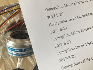
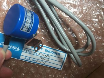
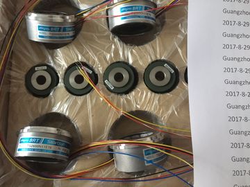
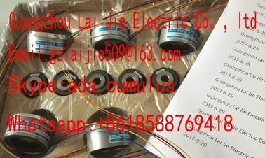
| Brand Name: | Tamagawa |
| Certification: | CE |
| Model Number: | TS5146N10 |
| Minimum Order Quantity: | 1pcs |
|---|---|
| Packaging Details: | carton |
| Delivery Time: | in stock |
| Payment Terms: | T/T, Western Union, MoneyGram |
| Supply Ability: | 100pcs/week |
| TAMAGAWA: | TAMAGAWA | TS5146N10: | TS5146N10 |
|---|---|---|---|
| Japan: | Japan | Material: | Iron |
| Color: | Black | Temperature: | 20-80 |
| Wire: | Wire |
TS3103N156
TS5146N10
TS3134N21
TS3667N2E6
TS5016N64
TS3643N212E5
TS530N33E9
TS2151N121E9
TS4503N2036E501
TS3134N22
OIS1000CT3L5V108
TS3667N3E7
TS5017N60
TS3643N233E8
TS5312-N250
TS2151N141E9
TS4506N1202E200
TS3134N317
OSE10243158
TS3667N3E8
TS5019N60
TS3653N11E2
TS5313N122
![]()
![]()
![]()
![]()
| n STEP 7 (PLC → Module status), the user can read data from the diagnostics buffer to determine the precise cause of error |
|
| Diagnostics data All diagnostics events are logged at the CPU and entered in → Diagnostics buffer. If an error |
|
| OB exists, the buffer is started. Direct access |
Denotes access of the CPU to a module via the → backplane bus, while bypassing the →
Process image.
electrically disconnected
The reference potential of the control and load voltage circuits at electrically isolated IO
modules are isolated galvanically, for example, using optocouplers, relay contacts or
transformers. IO circuits can be connected to a common reference potential.The reference potential of the control and load voltage circuits of non-isolated IO modules
are electrically interconnected.
Equipotential bonding
Electrical connection (equipotential conductor) of electrical equipment and external
conductive objects to the same or near to same potential, in order to prevent the
development of disturbance and dangerous potentials between those objects.
FREEZE
STEP 7 parameter for the SM 338; POS-INPUT position detection module. FREEZE is a
control command (function), used to freeze actual encoder values of SM 338.
Ground
The conductive earth whose electrical potential can be set equal to zero at any point.
Ground potential may be different from zero in the area of grounding electrodes. The term
"reference ground" is frequently used to describe this situation.
grounding
Grounding means, to connect an electrically conductive component via an equipotential
grounding system to a grounding electrode (one or several conductive components with low
impedance contact to earth.)
Hardware interrupt
Function initiated by interrupt-triggering modules, based on specific events in the process
(high or low limit violated, module has completed cyclic conversion of channels.)
The hardware interrupt is reported to the CPU, The CPU executes the assigned →
Organization block according to interrupt priority.
Hold last value (HLV)
The module retains the last value output before the CPU went into STOPSTEP 7 parameter for digital input modules. The input delay function is used to suppress
coupled disturbance. This includes pulse-shaped disturbance within the range from 0 ms to
the set input delay
The input delay tolerance is defined in the technical data of the module. The length of
suppressed pulse-shaped disturbance is determined by the length of the input delay.
The permissible input delay is determined by the line length between the encoder and the
module. Unshielded encoder supply lines of a grater length (more than 100 m) require a long