 |
| Place of Origin: | Japan |
| Brand Name: | Tamagawa |
| Certification: | CE |
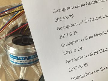
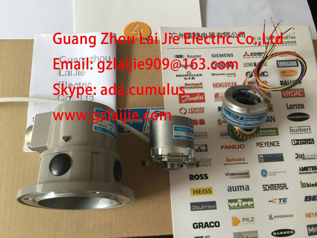
| Model Number: | TS2650N101E78 |
| Minimum Order Quantity: | 1pcs |
|---|---|
| Packaging Details: | carton |
| Delivery Time: | in stock |
| Payment Terms: | T/T, Western Union, MoneyGram |
| Supply Ability: | 100pcs/week |
| Tamagawa: | Tamagawa | TS2650N101E78: | TS2650N101E78 |
|---|---|---|---|
| Japan: | Japan | Color: | Black |
| Material: | Iron | Temperature: | 30mm |
| Dimension: | 30mm |
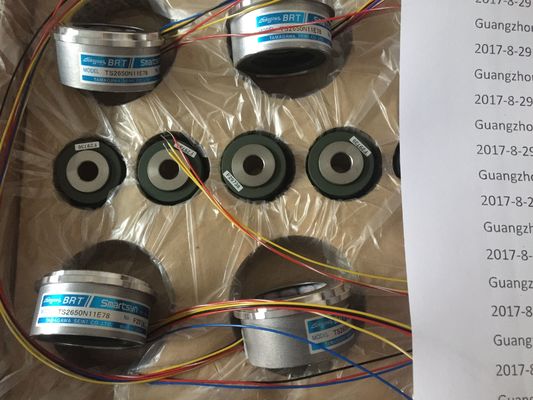
TS2650N101E78
Please contact with “Tommy” for the price
TS2142N1E63
TS2151N1E26
TS2151N1E45
TS2151N11E45
TS2640N321E64
TS2641N31E64
TS2650N1E78
TS2650N11E78
TS2650N101E78
TS2651N111E78
TS2651N181E78
TS5000N532
TS5000N632
TS5003N632
TS5005N122
TS5007N122
TS5007N635
TS5208N500
TS5208N510
TS5208N530
TS5208N569
TS5208N576
TS5210N450
TS5210N453
TS5210N458
TS5210N530
TS5210N54
TS5210N553
TS3684N1E3
TS3684N2E6
TS3684N3E8
TS3684N11E3
TS3684N12E6
TS3684N13E8
TS3617N1E3
TS3617N1E1
TS3617N1E2
TS3617N2E4
![]()
![]()
![]()
![]()
| to 60 °Cmax. 3 Am ax. 2 A | between channels and the backplane bus yes |
| max. 3 AElectrical isolation | between channelsv in groups of |
| vertical mounting positiont o 40 °C | Isolation test voltage 500 V DC |
Current consumption• from the backplane bus• from load voltage L+ (no-load)max. 70 mAmax. 90 mA
Power loss of the module typ. 5 WStatus display green LED per channel
Interrupts• Diagnostic interruptprogrammableDiagnostic functions
• Group error display• Channel error display (F)• Reading diagnostics data
programmablered LED (SF)red LED (F) per channelsupportedActuator selection dataOutput voltage• "1" signal
without series diodewith series diode
min. L + (- 0.8 V)min. L+ (-1.6 V)Output current• "1" signal
Rated value
Permitted range0.5 A
10 mA to 0.6 A1)• "0" signal (residual current) max. 0.5 mA
Output delay (resistive load)• "0" to "1" transition
• "1" to "0" transitionmax. 180 μs
max. 245 μsLoad resistance range 48 Ω to 3 kΩLamp load max. 5 W
Wiring two outputs in parallel• for redundant load control Only outputs with series diode and common referencepotential• for performance increase not supported
Control of a digital input supported1 binary input to IEC 61131, Type 2;Type 1, with disabled wire-break monitoringSwitching frequency• with resistive load• with inductive load to IEC 947-5-1, DC 13
• with lamp loadmax. 100 Hz
max. 2 Hzmax. 10 HzInternal limiting of the inductive shutdown voltage to typ. L + (-45 V)Short-circuit protection of the output yes, electronic• Threshold typ. 0.75 A to 1.5 AWiring of the actuators using a 20-pin front connector1) 5 mA to 0.6 A, with disabled wire-break monitoring
The output values of SM 322; DO 8 x DC 24V/0.5 A are determined by the CPU's operating state and the module's power supply. Table 3- 31 Influence of the CPU operating state and of the supply voltage L+ of SM 322; DO 8 24 VDC/0.5 A on output values.
The SM 322; DO 8 x DC 24 V/0.5 A can trigger diagnostic interrupts. For detailed information on the OBs and SFCs mentioned below, refer to the STEP 7 Online Help.
There is no default interrupt setting, i.e. interrupts are disabled if parameters are not set accordingly. Program the interrupt enable parameter in STEP 7.
Incoming error events (initial occurrence) and outgoing error events (error is cleared) are reported by means of diagnostics interrupt, if this interrupt is enabled. The CPU interrupts user program execution in order to process diagnostics interrupt OB82. You can call SFC51 or 59 in OB82 in the user program to view detailed diagnostics data output by the module. Diagnostics data remain consistent until the program exits OB82. The module acknowledges the diagnostics interrupt when the program exits OB82. See also SM 322; DO 8 x DC 24 V/0.5 A - Parameters (Page 178)