 |
| Place of Origin: | Japan |
| Brand Name: | Tamagawa |
| Certification: | CE |
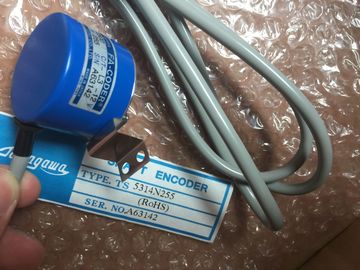
| Model Number: | TS5214N364 |
| Minimum Order Quantity: | 1pcs |
|---|---|
| Packaging Details: | carton |
| Delivery Time: | in stock |
| Payment Terms: | T/T, Western Union, MoneyGram |
| Supply Ability: | 100pcs/week |
| TAMAGAWA: | TAMAGAWA | Material: | Iron |
|---|---|---|---|
| Color: | Black | Temperature: | 20-90 |
| Dimension: | 20-90 | Japan: | Japan |
| Wire: | Wire | TS5214N364: | TS5214N364 |
TS5214N364
| The connection socket for the 4-pole connection plug is located on the underside of the | standardized connectors. Use prefabricated connecting cables for the connection. If you want to prepare communication cables The sensors and actuators of your plant are connected to |
| device for the following CPUs/interface modules. | |
| Standard, F-CPUs/compact CThe communication interfaces of the CPU/interface module are connected using | utomation system by means of front connectors. Wire the sensors and actuators to the front connector and then plug it |
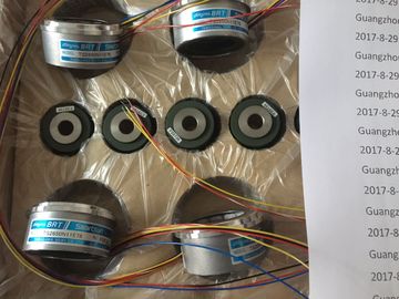
Guang Zhou Lai Jie Electric Co.,LTD
Please contact with “Tommy” for the price
TS4514N1828E200
TS3602N31E8
TS-1905N146E6
TS4603N1700E200
TS2087N12E9
TS2142N1E63
TS3617N381
TS4514N2002E200
TS3617N1E1
TS1922N3
TS4603N2002E200
TS2097N1E9
TS2151N1E26
TS3617N3E9
TS4514N2405E200
TS3617N1E2
TS2014N181E32
TS4603N7002E200
TS4602N6321E100
TS3617N2E4
TS3617N13E9
TS4515N1202E200
TS3617N11E1
TS2014N182E32
TS1505N55
TS4515N6000E200
TS4603N1000E100
TS3617N2E5
into the I/O module. You can eitheFront connector 35 mm with screw terminals
② Front connector 25 mm with push-in terminals
③ Front connector 35 mm with push-in terminals
Figure 6-8 Device versions of the front connectorThe three different front connectors are characterized as follows:
● 40 clamping points each
● Connection system: Screw terminal (for 35 mm modules only) or push-in terminal
● Module width: 35 mm or 25 mm
● If yoIf you want to supply load groups with the same potential (non-isolated), use the potential
bridges supplied for the front connector (with 35 mm width) for digital I/O modules. In four
locations: 9 and 29, 10 and 3d 40, the terminals can be bridged by
means of potential bridges. Advantage: Reduction of the wiring effort
The use of potential bridges depends on the relevant module used.
Potential bridges must not be used for 230 V modules. Use the potential bridges only with
a maximum supply voltage of 24 V DC. The current capacity pThe front connectors for 25 mm modules have no potential bridges.
Observe the instructions and wiring rules in the product manual of the respective I/O
module when using potential bridgIn the delivery state a coding element is located in the module. When the front connector
is first inserted into the I/O module, a part of the coding element clips onto the front
connector. When the front connector is removed from the I/O module, one part of the
coding element remains in the front connector, and the other part remains in the I/O
module. The insertion of a front connector that is not sui, and the other part remains in the I/O
module. The insertion of a front connector that is not suited to the module is thereby
mechanically prevented. This ensures, for example, that the front connectoctor with the
coding element of a digital module cannot be inserted into an analog In as-delivered condition, a fail-safe module not only has a mechanical coding element but
also an electronic rewritable memory for the PROFIsafe address. This is the electronic
coding elementWhen the front connector is inserted in the F-module, the electronic coding element latches
fully into place in the front connector. If you remove the front connector from the F-module,
the memory with the PROFIule remains in the front
connector (see section Replacing a front connector (Page 283))You can find additional information on the coding element in the section Coding element on
the I/O module and on the front connectorAdditional information on the use of the potential bridges can be found in the product manual
for the respective I/O moduleThe I/O modules are installed on the mounting rail.
● The supply voltages are turned offThe cables are prepared according to the clamping technology used; take the Wiring
rules (Page 134) into account for this purpose● Stripping tool
● 3 to 3.5 mm Proceed as follows to wire the front connector:
1. As needed, switch off the load current supply.
2. Place the included cable strain relief (cable tie) for the cable harness into the front
connector (Figure 1).
Bring the front connector into the pre-wiring position. To do this, hook the front connector
into the bottom of the I/O module and swivel the front connector upward until the front
connector latches (Figure 3).Result: In this position, the front connector still protrudes from the I/O module (Figure 4).