|
| Place of Origin: | Japan |
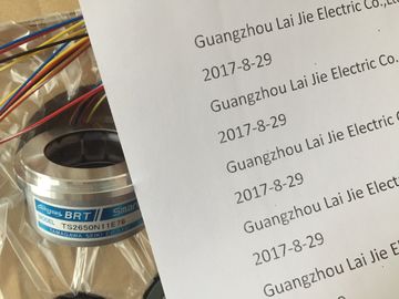
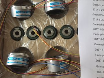
| Brand Name: | Tamagawa |
| Certification: | CE |
| Model Number: | TS5312N512 |
| Minimum Order Quantity: | 1pcs |
|---|---|
| Packaging Details: | carton |
| Delivery Time: | in stock |
| Payment Terms: | T/T, Western Union, MoneyGram |
| Supply Ability: | 100pcs/week |
| TAMAGAWA: | TAMAGAWA | TS5312N512: | TS5312N512 |
|---|---|---|---|
| Color: | Black | Material: | Iron |
| Temperature: | 20-90 | Wire: | Wire |
| Dimension: | 80mm | Japan: | Japan |
TS5312N512-2000C/TOSE.5KN-6-12-108
| Insert the wire into the push-in terminal as far as it will go.To connect a wire without end sleeve, follow these steps: | |
| trip 8 to 11 mm of the wires. 2. Using a screwdriver, press the spring release and insert the wire into as far as it will go. |
|
| ull the screwdriver out of to uninstall the connection plug, you need a screwdriver. With the screwdriver, pry the |
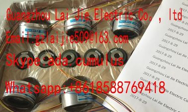
Guang Zhou Lai Jie Electric Co.,LTD
Please contact with “Tommy” for the price
TS1505N55
TS4515N6000E200
TS4603N1000E100
TS3617N2E5
TS3617N40E3
TS4515N2405E200
TS3617N1E3
TS2014N185E32
TS4602N1000E200
TS4603N1000E200
TS3617N2E6
TS5214N566
TS5205N450
TS5213N551
TS5208N122
TS5208N23
TS5778N171
TS5210N53
TS5320N510
TS5000N632
TS5212N510
TS5213N510
TS5312N616
TS208N101
TS5208N130
TS5213N530
TS5013N68
TS5214N566
TS5200N500
TS5305N616
TS5669N220
TS5214N564
TS5246N158
TS5667N650
TS5213N551
TS5668N20
TS5667N120
TS5667N420
TS5246N160
TS5312N512
TS5208N122
TS5641N151
TS5270N15
connection plug out of the CPU/interface moduleIn the delivery condition of the system power supplies/load current supplies, power
connectors are inserted. The modules and the associated power connectors are coded. The
coding is effected by means of two cof two coding elements - one coding element is located in the
module, and the other in the power connector. The system power supplies/load current
supplies use identical power connectors for the voltage connectie insertion of a power connector into a different type of
system power supply/load current supplye insertion of a power connector into a different type of
system power supply/load current supplybutton of the power cable connector (Figure 1). Remove the
power cable connector from the front of the modulLoosen the screw on the front of the connector. This loosens the housing latch and the
cable relief. With a tightened screw the connector's cover can't be removed (Figure 2).
4. Pry off the connector cover using a sStrip the cable sheathing to a length of 35 mm and the conductors to a length of 7 to 8
mm, and bring them up to the end sleeves.
Connect the wires in the connector according to the connection diagram (Figure 4).
7. Close the cover (Figure 5).
8. Retighten the screw (Figure 6). This effects a strain relief on the linesConnecting the supply voltage to a system power supply/load current supply (2)
9. Insert the power connector into the module, until the latch engagAdditional information about connecting the 24 V DC output voltage of the load voltage
supply modules is available in the manuals of the corresponding moduleThe load current supply is equipped with a plug-in 24 V DC output terminal (behind the front
cover at the bottom). You connect the wires for the supply voltage of the CPU/interface
module to this terminal.
The load current supply is equipped with a plug-in 24 V DC output terminal (behind the front
cover at the bottom). You connect the wires for the supply voltage of the CPU/interface
module to this terminal. ● Only wire the connection plug when the supply voltage is turned off.
● The connection plug for connecting the supply voltage to the CPU / interface module is
already mounted, see section Connecting the supply voTo connect the supply voltage, follow these steps:
1. Open the front flap of the load current supply and pull the 24 V DC output terminal
downwards.
2. Connect the 24 V DC output terminal to the wires of the 4-pole coConnection on the underside of the device