 |
| Place of Origin: | Japan |
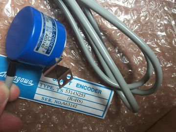
| Brand Name: | Tamagawa |
| Certification: | CE |
| Model Number: | TS5017N56 |
| Minimum Order Quantity: | 1pcs |
|---|---|
| Packaging Details: | carton |
| Delivery Time: | in stock |
| Payment Terms: | T/T, Western Union, MoneyGram |
| Supply Ability: | 100pcs/week |
| TAMAGAWA: | TAMAGAWA | Material: | Iron |
|---|---|---|---|
| TS5017N56: | TS5017N56 | Japan: | Japan |
| Color: | Black | Temperature: | 20-90 |
| Dimension: | 80mm | Wire: | Wire |
TS5017N56
| Order number 3RK7243-2AA30-0XB0 | Max. 250 mA, SIMATIC backplane bus supply voltage 5 V DC |
| Interfaces Maximum current consumption |
Max. 100 mA Pin assignment See section Electrical connections of the AS-i master CM 1243-2 (Page 819) |
| From the SIMATIC backplane bus From the AS-i cable |
Conductor cross-section 0.2 mm2 (AWG 24) ... 3.3 mm2 (AWG 12) ASI connector tightening torque 0.56 Nm |
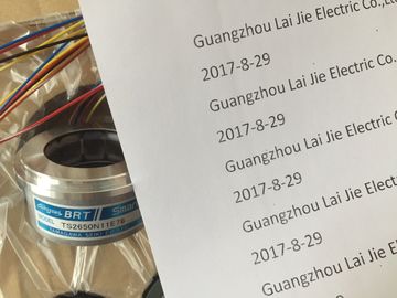
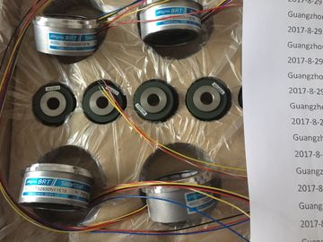
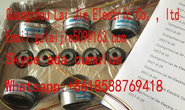
Guang Zhou Lai Jie Electric Co.,LTD
Please contact with “Tommy” for the price
TS1981N53E19
TS1981N56E19
TS1981N56E19
TS1982N126E6
TS1982N128E6
TS1982N53E6
TS1982N56E18
TS1983N146E5
TS252N30E1
TS3503N11E43
TS3062E3
TS3092N11E12
TS3095N2
TS3103N156
TS3103N178
TS3103N255
TS3103N302
TS3103N40
TS3132N32
TS3134N21
TS3134N22
TS3134N317
TS3134N52
TS3166
TS3166N43
TS3212N32
TS3214N12
TS3214N13
TS3214N15
TS3214N16
TS3214N44
TS3218
TS3218N42
TS3218N5
TS3250E12
TS3275N125
TS3153N15E18
TS3602N213E8
SIMATIC backplane bus supply voltage 5 V DC
Max. 100 mA
Pin assignment See section Electrical connections of the AS-i master CM
1243-2 (Page 819)
Conductor cross-section 0.2 mm2 (AWG 24) ... 3.3 mm2 (AWG 12)
ASI connector tightening torque 0.56 Nm
The AS-i master CM 1243-2 is supplied over the communications bus of the . This
means that a diagnostics message can still be sent to the follog failure of the
AS-i supply voltage. The connection to the communications bus is on the right-hand side of
the AS-i master CM 1243-2.
The removable terminal for connecting the AS-i cable is located behind the lower cover on
the front of the AS-i master CM 1243-2The current carrying capacity of the connection contacts is max. 8 A. If this value is
exceeded on the AS-i cable, the AS-i master CM 1243-2 must not be "looped in" to the ASi
cable, but must instead be connected via a spur line (only one connection pair assigned
on the AS-i master CM 1243-2).
You will find additional information on connecting the AS-i cable in the section "Installation,
connection and commissioning of the modules" in the manual "AS-i Master CM 1243-2 and
AS-i data decoupling unit DCM 1271 for SIMATIC ".
Type RS485 (2-wire half-duplex)
Common mode voltage range -7 V to +12 V, 1 second, 3 VRMS continuous
Transmitter differential output voltage 2 V min. at RL = 100 Ω
1.5 V min. at RL = 54 Ω
Termination and bias 10K to +5 V on B, RS485 Pin 3
10K to GND on A, RS485 Pin 4
Optional termination Short Pin TB to Pin T/RB, effective termination impedance is 127 Ω,
connects to RS485 Pin 3
Short Pin TA to Pin T/RA, effective termination impedance is 127 Ω,
connects to RS485 Pin 4
Receiver input impedance 5.4K Ω min. including termination
Receiver threshold/sensitivity +/- 0.2 V min., 60 mV typical hysteresis
Isolation
RS485 signal to chassis ground
RS485 signal to CPU logic common
500 VAC, 1 minute
Cable length, shielded 1000 m max.
Baud rate 300 baud, 600 baud, 1.2 kbits, 2.4 kbits, 4.8 kbits, 9.6 kbits (default),
19.2 kbits, 38.4 kbits, 57.6 kbits, 76.8 kbits, 115.2 kbits,
Parity No parity (default), even, odd, Mark (parity bit always set to 1),
Space (parity bit always set to 0)
Number of stop bits 1 (default), 2
Flow control Not supported
Wait time 0 to 65535 m Connect "TA" and TB" as shown to terminate the network. (Terminate only the end
devices on the RS485 network.)
② Use shielded twisted pair cable and connect the cable shield to ground.
You terminate only the two ends of the RS485 network. The devices in between the two end
devices are not terminated or biased. See the System Manual section on "Biasing
and terminating an RS485 network connector"
Table A- 220 Connector pin locations for CB 1241 RS485 (6ES7 241-1CH30-Type RS232 (full-duplex)
Transmitter output voltage +/- 5 V min. at RL = 3K Ω
Transmit output voltage +/- 15 VDC max.
Receiver input impedance 3 K Ω min.
Receiver threshold/sensitivity 0.8 V min. low, 2.4 max. high
0.5 V typical hysteresis
Receiver input voltage +/- 30VDC max.
Isolation
RS 232 signal to chassis ground