|
| Place of Origin: | Japan |
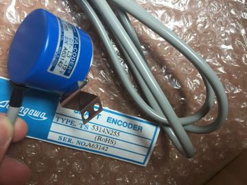
| Brand Name: | Tamagawa |
| Certification: | CE |
| Model Number: | TS2025N471E69 |
| Minimum Order Quantity: | 1pcs |
|---|---|
| Packaging Details: | carton |
| Delivery Time: | in stock |
| Payment Terms: | T/T, Western Union, MoneyGram |
| Supply Ability: | 100pcs/week |
| TAMAGAWA: | TAMAGAWA | Material: | Iron |
|---|---|---|---|
| Color: | Black | Japan: | Japan |
| Temperature: | 20-90 | Dimension: | 80mm |
| Wire: | Wire | TS2025N471E69: | TS2025N471E69 |
TS2025N471E69
| Some of the 24V power input ports in the PLC system are interconnected, | that are interconnected when designated as not isolated in the data sheets. All non-isolated |
| common circuit connecting multiple M terminals. The CPU 24V power supply input, | M terminals must connect to the same external reference potential. |
| the SM relay coil power input, and a non-isolated analog power supply input are examples of circuits |
Connecting non-isolated M terminals to different reference potentials will cause unintended |
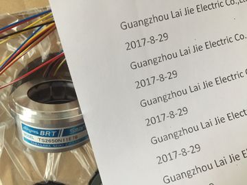
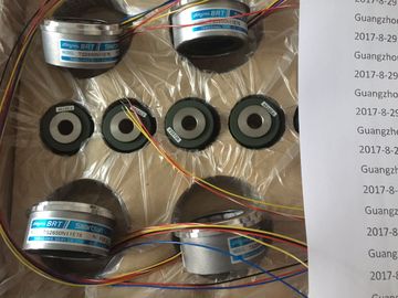
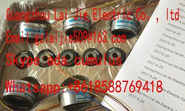
Guang Zhou Lai Jie Electric Co.,LTD
Please contact with “Tommy” for the price
TS4503N1022E200
TS4503N1202E200
TS4503N1205E200
TS4503N1828E100
TS4503N2000E100
TS4503N2070E100
TS4503N2202E200
TS4503N2036E501
TS4506N1202E200
TS4507N1002E200
TS4507N1202E200
TS4507N1205E200
TS4507N1229E200
TS4507N2000E100
TS4507N2070E100
TS4507N2405E200
TS4507N6205E200
TS4507N8029E200
TS4509N1002E200
TS4509N1202E200
TS4509N1831E200
TS4509N2002E200
TS4509N2405E200
TS4509N7000E100
TS4514N1021E200
TS4514N1407E200
TS4514N1828E200
TS4514N2002E200
TS4514N2405E200
TS4515N1202E200
TS4515N2405E200
TS4515N6000E200
TS4602N1000E200
TS4602N6321E100
TS4603N1000E100
TS4603N1000E200
TS4603N1532E200
current flows that may cause damage or unpredictable operation in the PLC and connected
equipment.
Such damage or unpredictable operation could result in death, severe personal injury
and/or property damage.
Always be sure that all non-isolated M terminals in a PLC system are connected to the
same reference potential. nformation about the power budgets of the CPUs and the power requirements of the signal
modules is provided in the technical specificationsThe following example shows a sample calculation of the power requirements for a
configuration that includes one CPU 1214C AC/DC/Relay, one SB 1223 2 x 24 VDC Input/ 2
x 24 VDC Output, one CM 1241, three SM 1223 8 DC In/8 Relay Out, and one SM 1221 8
DC In. This example has a total of 48 inputs and 36 outputs.
Note
The CPU has already allocated the power required to drive the internal relay coils. You do
not need to include the internal relay coil power requirements in a power budget calculation.
The CPU in this example provides sufficient 5 VDC current for the SMs, but does not provide
enough 24 VDC current from the sensor supply for all of the inputs and expansion relay
coils. The I/O requires 456 mA and the CPU provides only 400 mA. This installation requires
an additional source of at least 56 mA at 24 VDC power to operate all the included 24 VDC
inputs and outputs. CPU 1214C, 14 inputs - 14 * 4 mA = 56 mA
1 SB 1223 2 x 24 VDC Input/ 2 x 24
VDC Output
50 mA 2 * 4 mA = 8 mA
1 CM 1241 RS422/485, 5 V power 220 mA
3 SM 1223, 5 V power 3 * 145 mA = 435 mA -
1 SM 1221, 5 V power 1 * 105 mA = 105 mA -
3 SM 1223, 8 inputs each - 3 * 8 * 4 mA = 96 mA
3 SM 1223, 8 relay coils each - 3 * 8 * 11 mA = 264 mA
1 SM 1221, 8 inputs each - 8 * 4 mA = 32 mA
Total requirements 810 mA 456 mA
Equals
Current balance 5 VDC 24 VDC
Current balance total 790 mA (56 mA)
Form for calculating your power budget
Use the following table to determine how much power (or current) the CPU can
provide for your configuration. Refer to the technical specifications (Page 699) for the power
budgets of your CPU model and the power requirements of your signal modules.