 |
| Place of Origin: | Japan |
| Brand Name: | Tamagawa |
| Certification: | CE |
| Model Number: | TS5016N64 |
| Minimum Order Quantity: | 1pcs |
|---|---|
| Packaging Details: | carton |
| Delivery Time: | in stock |
| Payment Terms: | T/T, Western Union, MoneyGram |
| Supply Ability: | 100pcs/week |
| TAMAGAWA: | TAMAGAWA | TS5016N64: | TS5016N64 |
|---|---|---|---|
| Japan: | Japan | Color: | Black |
| Material: | Iron | Temperature: | 20-90 |
| Dimension: | 60mm | Wire: | Wire |
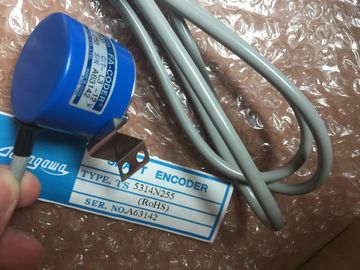
TS5016N64
Guang Zhou Lai Jie Electric Co.,LTD
Please contact with “Tommy” for the price
TS3684N3E8
TS3684N11E3
TS3684N12E6
TS3684N13E8
TS3617N1E3
TS3617N1E1
TS3617N1E2
TS3617N2E4
TS3617N2E5
TS3617N2E6
TS3617N2E7
TS3617N3E8
TS3617N3E9
TS3617N3E1
TS3617N11E3
TS3617N11E1
TS3617N11E2
TS3617N12E4
TS3617N12E5
TS3617N12E6
TS3617N12E7
TS3617N13E8
TS3617N13E9
TS3617N13E1
TS3653N1E1
TS3653N1E2
TS3653N1E3
TS3653N2E4
TS3653N2E5
TS3653N2E6
TS3653N3E7
TS3653N3E8
TS3653N3E9
![]()
![]()
![]()
![]()
| P1120=(0 to 650.00) 7. Ramp down time (optional) |
Set the serial link reference frequency: P2000=(1 to 650 Hz) |
| This the time in seconds that it takes the motor to decelerate to a complete stop.Set the baud rate of the RS485 serial interface: P2010 Index 0= 4 (2400 baud) 5 (4800 baud |
Set tSet the baud rate of the RS485 serial interface: P2010 Index 0= 4 (2400 baud) 5 (4800 baud |
9600 baud)
7 (19200 baud
8 (38400 baud)
9 (57600 baud)
12 (115200 baud)
11. Enter the Slave address.
Each drive (a maximum of 31) can be operated over the bus.
P2011 Index 0=(0 to 31)
12. Set the serial link timeout.
This is the maximum permissible period between two incoming data
telegrams. This feature is used to turn off the inverter in the event of a
communications failure. Timing starts after a valid data telegram has been
received. If a further data telegram is not received within the specified time
period, the inverter will trip and display fault code F0070. Setting the value to
zero switches off the control.
P2014 Index 0=(0 to 65,535 ms)
0=timeout disabled
13. Transfer the data from RAM to EEPROM: P0971=1 (Start transfer) Save the changes
to the paraer settings to EEPROM A CPU operating as a Modbus RTU master (or Modbus TCP client) can read/write both
data and I/O states in a remote Modbus RTU slave (or Modbus TCP server). Remote
data can be read and processed in the user program.
● A CPU operating as a Modbus RTU slave (or Modbus TCP server) allows a supervisory
device to read/write both data and I/O states in a remote CPU. The supervisor device can
write new values in remote CPU memory that can be processed in the user program.
Table 12- 45 Read data functions: Read remote I/O and program data
Modbus function code Read slave (server) functions - standard Modbus function codes 08 and 11 provide slave device communication diagnostic
information.
● Modbus function code 0 broadcasts a message to all slaves (with no slave response).
The broadcast function is not available for Modbus TCP, because communication is
connection basedModbus function codes 08 and 11 provide slave device communication diagnostic
information.
● Modbus function code 0 broadcasts a message to all slaves (with no slave response).
The broadcast function is not available for Modbus TCP, because communication is
connection basedThe actual number of Modbus memory addresses available depends on the CPU model,
how much work memory exists, and how much CPU memory is used by other program data.
The table below gives the nominal value of the address rangeModbus RTU (Remote Terminal Unit) is a standard network communication protocol that
uses the RS232 or RS485 electrical connection for serial data transfer between Modbus
network devices. You can add PtP (Point to Point) network ports to a CPU with a RS232 or
RS485 CM or a RS485 CB.
Modbus RTU uses a master/slave network where all communications are initiated by a
single Master device and slaves can only respond to a master’s request. The master sends a
request to one slave address and only that slave address responds to the command.
Modbus TCP communication
Modbus TCP (Transmission Control Protocol) is a standard network communication protocol
that uses the PROFINET connector on the CPU for TCP/IP communication. No additional
communication hardware module is required.
Modbus TCP uses Open User Communications (OUC) connections as a Modbus
communication path. Multiple client-server connections may exist, in addition to the
connection between STEP 7 and the CPU. Mixed client and server connections are
supported up to the maximum number of connections allowed by the CPU model
(Page 424).
Each MB_SERVER connection must use a unique instance DB and IP port number. Only 1
connection per IP port is supported. Each MB_SERVER (with its unique instance DB and IP
port) must be executed individually for each connectionModbus TCP will only operate correctly with CPU firmware release V1.02 or later. An
attempt to execute the Modbus instructions on an earlier firmware version will result in an