|
| Place of Origin: | Japan |
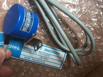
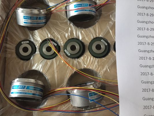
| Brand Name: | Tamagawa |
| Certification: | CE |
| Model Number: | TS5017N60 |
| Minimum Order Quantity: | 1pcs |
|---|---|
| Packaging Details: | carton |
| Delivery Time: | in stock |
| Payment Terms: | T/T, Western Union, MoneyGram |
| Supply Ability: | 100pcs/week |
| TAMAGAWA: | TAMAGAWA | Material: | Iron |
|---|---|---|---|
| Color: | Black | Japan: | Japan |
| Temperature: | 20-90 | Dimension: | 80mm |
| Wire: | Wire | TS5017N60: | TS5017N60 |
TS5017N60
| 7003 A disconnect operation has successfully completed (Only valid for one PLC scan). | |
| 80C8 The server did not respond in the assigned time. MB_CLIENT must receive a response using the | |
| transaction ID that was originally transmitted within the assigned time or this error is returned. |
Guang Zhou Lai Jie Electric Co.,LTD
Please contact with “Tommy” for the price
TS5850N60
TS3630N1303E9
TS5008N66
TS2650N1E78
TS374
TS1981N53E19
61347
TS3653N3E8
TS5850N64
TS3630N1309E5
TS5010N
TS2650N11E78
TS3762N15E4
TS1981N56E19
TS3653N3E9
TS5850N70
TS3630N1306
TS5013N69
TS2650N101E78
TS4126N1017E235
TS1981N56E19
TS3653N13E9
TS5N2E18
TS3630N1E1
TS5013N61
TS2651N111E78
TS4127N1017E215
TS1982N126E6
transaction ID that was originally transmitted within the assigned time or this error is returned. transaction ID that was originally transmitted within the assigned time or this error is returned. Check the
connection to the Modbus server device.
This error is only reported after any configured retries (if applicable) have been attempted.
8188 Invalid mode value
8189 Invalid data address value
818A Invalid data length value
818B Invalid pointer to the DATA_PTR area. This can be the combination of MB_DATA_ADDRESS +
MB_DATA_LEN.
818C Pointer to a optimized DATA_PTR area (must be a standard DB area or M memory area)
8200 The port is busy processing an existing Modbus request.
8380 Received Modbus frame is malformed or too few bytes have been received. The assigned Connection ID paraer is different from the ID used for previous requests. There can only
be a single Connection ID used within each MB_CLIENT instance DB.
This is also used as an internal error if the Modbus TCP protocol ID received from a server is not 0.
8388 A Modbus server returned a quantity of data that is different than what was requested. This applies to
Modbus functions 15 or 16 only.
1 In addition to the MB_CLIENT errors listed above, errors can be returned from the underlying T block communication
instructions (TCON, TDISCON, TSEND, and TRCV)MB_SERVER communicates as a
Modbus TCP server through the
PROFINET connector on the
CPU. No additional communication
hardware module is required.
MB_SERVER can accept a request to
connect with Modbus TCP client ,
receive a Modbus function request, and
send a response messageMB_SERVER attempts to make a "passive" connection with a partner device.
This means that the server is passively listening for a TCP connection request
from any requesting IP address.
If DISCONNECT = 0 and a connection does not exist, then a passive
connection can be initiated.
If DISCONNECT = 1 and a connection exists, then a disconnect operation is
initiated. This allows your program to control when a connection is accepted.
Whenever this input is enabled, no other operation will be attempted.
CONNECT_ID IN UInt CONNECT_ID uniquely identifies each connection within the PLC. Each
unique instance of the MB_CLIENT or MB_SERVER instruction must contain a
unique CONNECT_ID paraer. Default value = 502: The IP port number that identifies the IP port that will be
monitored for a connection request from a Modbus client.
These TCP port numbers are not allowed for a MB_SERVER passive
connection: 20, 21, 25, 80, 102, 123, 5001, 34962, 34963, and 34964.
MB_HOLD_REG IN_OUT Variant Pointer to the MB_SERVER Modbus holding register: The holding register
must either be a standard global DB or a M memory address. This memory
area is used to hold the values a Modbus client is allowed to access using
Modbus register functions 3 (read), 6 (write), and 16 (write).
NDR OUT Bool New Data Ready: 0 = No new data, 1 = Indicates that new data has been
written by a Modbus client
DR OUT Bool Data Read: 0 = No data read, 1 = Indicates that data has been read by a
Modbus client.
ERROR OUT Bool The ERROR bit is TRUE for one scan, after MB_SERVER execution was
terminated with an error. The error code value at the STATUS paraer is
valid only during the single cycle where ERROR = TRUE.
STATUS OUT Word Execution condition code
MB_SERVER allows incoming Modbus function codes (1, 2, 4, 5, and 15) to read or write
bits and words directly in the input process image and output process image of the
CPU. For data transfer function codes (3, 6, and 16), the MB_HOLD_REG paraer must
be defined as a data type larger than a byte. The following table shows the mapping of
Modbus addresses to the process image in the CPU. ncoming Modbus message function codes function codes (3, 6, and 16) read or write words
in a Modbus holding register which can be an M memory address range or a data block. The
type of holding register is specified by the MB_HOLD_REG paraer.
Note
MB_HOLD_REG paraer assignment
The Modbus Holding Register can be in a standard global DB or a M memory address.
For A Modbus holding register in M memory, use the standard Any Pointer format. This is in
the format P#"Bit Address" "Data Type" "Length". An example would be P#M1000.0 WORD
500 The following table shows examples of Modbus address to holding register mapping used for
Modbus function codes 03 (read words), 06 (write word), and 16 (write words). The actual
upper limit of DB addresses is determined by the maximum work memory limit and M
memory limit, for each CPU modelMultiple server connections may be created. This permits a single PLC to establish
concurrent connections to multiple Modbus TCP clients.
A Modbus TCP server can support concurrent connections up to the maximum number of
Open User Communications connections allowed by the PLC. The total number of
connections for a PLC, including Modbus TCP Clients and Servers, must not exceed the
maximum number of supported Open User Communications connections (Page 424). The
Modbus TCP connections may be shared between Client and/or Server type connections.
Individual server connection must follow these rules:
● Each MB_SERVER connection must use a distinct instance DB.