|
| Place of Origin: | Japan |
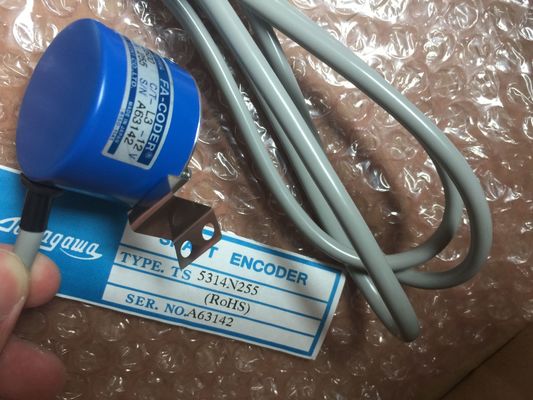
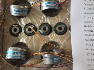
| Brand Name: | Tamagawa |
| Certification: | CE |
| Model Number: | TS2151N141E9 |
| Minimum Order Quantity: | 1pcs |
|---|---|
| Packaging Details: | carton |
| Delivery Time: | in stock |
| Payment Terms: | T/T, Western Union, MoneyGram |
| Supply Ability: | 100pcs/week |
| TAMAGAWA: | TAMAGAWA | Material: | Iron |
|---|---|---|---|
| Color: | Black | Japan: | Japan |
| Dimension: | 80mm | Temperature: | 20-90 |
| Wire: | Wire | TS2151N141E9: | TS2151N141E9 |
TS2151N141E9
| This example shows a Modbus client request to write the output image. Network |
The example below shows how the outputs of the first and second client requests can be used to coordinate executionThe example shows both clients writing to the same memory area. |
| Modbus function 15 - Write output image bits You must ensure that each individual Modbus TCP request finishes execution. | Also, a returned error is captured which is optional. |
| This coordination must be provided by your program. |
Network 1: Modbus function 3 - Read holding register words There are two versions of the Modbus RTU instructions available in STEP 7 |
Guang Zhou Lai Jie Electric Co.,LTD
Please contact with “Tommy” for the price
TS252N30E1
AU6270N103E63
TS3653N94E5
TS5208N141E78
TS3630N22E4
TS5146N10
TS5208N500
TS4502N2000E100
TS3503N11E43
TS3653N181E8
TS3684N1E3
TS3631N1E1
TS5146N11
TS5208N510
TS4503N1000E200
TS3062E3
TS3658N3
TS3684N13E8
TS3636N6
TS-5170-N20
TS5208N530
TS4503N1007E200
TS3092N11E12
AU6550N2062
TS3664N1E1
TS3617N1E3
TS3641N1E1
TS5207N530
TS5208N569
TS4503N1022E100
ersion 1 was initially available in STEP 7 Basic V10.5.
● Version 2 is available in STEP 7 Basic/Professional V11. The version 2 design adds REQ
and DONE parameters to MB_COMM_LOAD. Also, the MB_ADDR parameter for
MB_MASTER and MB_SLAVE now allows a UInt value for extended addressing.
For compatibility and ease of migration, you can choose which instruction version to insert
into your user program. Do not use both 1.x and 2.y instruction versions in the same CPU program. Your program's
Modbus instructions must have the same major version number (1.x, 2.y, or V.z). The
individual instructions within a major version group may have different minor versions (1.x).
Click the icon on the instruction tree task card to enable the headers and columns
of the instruction tree.To change the version of the Modbus
instructions, select the version from the dropdown
list. You can select the group or
individual instructions.
When you use the instruction tree to place a Modbus instruction in your program, a new FB
instance is created in the project tree. You can see new FB instance in the project tree under
PLC_x > Program blocks > System blocks > Program resources.
To verify the version of a Modbus instruction in a program, you must inspect project tree
properties and not the properties of a box displayed in the program editor. Select a project
tree Modbus FB instance, right-click, select "Properties", and select the "Information" page to
see the Modbus instruction version number. The MB_COMM_LOAD instruction configures a
PtP port for Modbus RTU protocol
communications. Modbus port hardware options:
Install up to three CMs (RS485 or RS232), plus
one CB (R4845). An instance data block is
assigned automatically when you place the
MB_COMM_LOAD instruction in your program. A low to high (positive edge) signal starts the operation.
(Version 2.0 only)
PORT IN Port After you install and configure a CM or CB communication device, the
port identifier appears in the parameter helper drop-list available at the
PORT box connection. The assigned CM or CB port value is the device
configuration property "hardware identifier". The port symbolic name is
assigned in the "System constants" tab of the PLC tag table.
BAUD IN UDInt Baud rate selection:
300, 600, 1200, 2400, 4800, 9600, 19200, 38400, 57600, 76800, 115200,
all other values are invalid
PARITY IN UInt Parity selection:
0 – None
1 – Odd
2 – Even
FLOW_CTRL IN UInt Flow control selection:
0 – (default) no flow control
1 – Hardware flow control with RTS always ON (does not apply to
RS485 ports)
2 – Hardware flow control with RTS switched
RTS_ON_DLY IN UInt RTS ON delay selection: