|
| Place of Origin: | Japan |
| Brand Name: | Tamagawa |
| Certification: | CE |
| Model Number: | TS2640N141E172 |
| Minimum Order Quantity: | 1pcs |
|---|---|
| Packaging Details: | carton |
| Delivery Time: | in stock |
| Payment Terms: | T/T, Western Union, MoneyGram |
| Supply Ability: | 100pcs/week |
| TAMAGAWA: | TAMAGAWA | Material: | Iron |
|---|---|---|---|
| Color: | Black | Japan: | Japan |
| TS2640N141E172: | TS2640N141E172 | Wire: | Wire |
| Dimension: | 70mm | Temperature: | 20-90 |
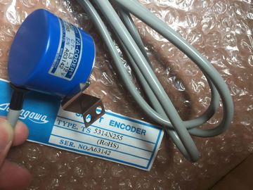
TS2640N141E172
| Set the cursor at the right side of the DB name (after the quote character) and enter a period character. |
reference discussed above except that the Extended_Addressing variable is a boolean value. |
| Select "MB_SLAVE_DB.HR_Start_Offset" from the drop list. |
The boolean value must be written by an output coil and not a move box. |
| The Extended_Addressing variable is accessed in a similar way as the HR_Start_Offset | Modbus slave addressing can be configured to be either a single byte (which is the Modbus standard) or double byte. |
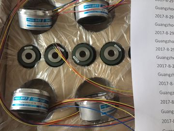
Guang Zhou Lai Jie Electric Co.,LTD
Please contact with “Tommy” for the price
TS2025N471E69
TS2014N181E32
TS5208N111E78
TS5208N141E78
TS3684N1E3
TS3684N13E8
TS3617N1E3
TS3617N1E1
TS3617N1E2
TS3617N2E4
TS3630N11E1
TS3664N2E4
TS3653N13E7
TS3653N12E6
TS3653N2E5
TS3624N2E3
TS3653N13E9
TS3653N2E6
TS3653N3E7
TS3653N3E8
TS3653N3E9
TS1980N43E12
TS1980N56E12
TS1981N134E9
TS1981N53E19
TS1981N56E19
TS1981N56E19
TS1982N126E6
TS1982N128E6
TS1982N53E6
Extended addressing is used to address more than 247 devices
within a single network. Selecting extended addressing allows you to address a maximum of
64000 addresses. A Modbus function 1 frame is shown below as an example.
The receiver issued a flow control request to suspend an active transmission and never reenabled
the transmission during the specified wait time.
This error is also generated during hardware flow control when the receiver does not assert
CTS within the specified wait time.
80D2 The transmit request was aborted because no DSR signal is received from the DCE.
80E0 The message was terminated because the receive buffer is full.
80E1 The message was terminated as a result of a parity error.
80E2 The message was terminated as a result of a framing error.
80E3 The message was terminated as a result of an overrun error.
80E4 The message was terminated as a result of the specified length exceeding the total buffer
size.
8180 Invalid port ID value or error with MB_COMM_LOAD instruction
8186 Invalid Modbus station address
8187 Invalid pointer to MB_HOLD_REG DB: Area is too small
818C Invalid MB_HOLD_REG pointer to M memory or DB (DB area must allow both symbolic and
direct address) CRC error
8381 01 Function code not supported or not supported within broadcasts
8382 03 Data length error
8383 02 Data address error or address outside the valid range of the
DATA_PTR area
8384 03 Data value error
8385 03 Data diagnostic code value not supported (function code 08)
1 In addition to the MB_SLAVE errors listed above, errors can be returned from the underlying PtP communication
MB_COMM_LOAD is initialized during start-up by using the first scan flag. Execution of
MB_COMM_LOAD in this manner should only be done when the serial port configuration will
not change at runtime.
Network 1 Initialize the RS485 module parameters only once during the first scan.
One MB_MASTER instruction is used in the program cycle OB to communicate with a single
slave. Additional MB_MASTER instructions can be used in the program cycle OB to
communicate with other slaves, or one MB_MASTER FB could be re-used to communicate
with additional slaves. Network 3 This is an optional network that just shows the values of the first 3 words once the
read operation is done. Write 64 bits to the output image register starting at slave address Q2.0. MB_COMM_LOAD shown below is initialized each time "Tag_1" is enabled.
Execution of MB_COMM_LOAD in this manner should only be done when the serial port
configuration will change at runtime, as a result of HMI configuration. Network 1 Initialize the RS485 module parameters each time they are changed by an HMI
device. MB_SLAVE shown below is placed in a cyclic OB that is executed every 10ms. While this
does not give the absolute fastest response by the slave, it does provide good performance
at 9600 baud for short messages (20 bytes or less in the request).
Network 2 Check for Modbus master requests during each scan. The Modbus holding
register is configured for 100 words starting at MW1000. Using the CP 1242-7 communications processor, the can be connected to GSM
networks. The CP 1242-7 allows WAN communication from remote stations with a control
center and inter-station communication.
Inter-station communication is possible only via a GSM network. For communication
between a remote station and a control room, the control center must have a PC with
Internet access. The CP 1242-7 supports the following services for communication via the GSM network: