 |
| Place of Origin: | Japan |
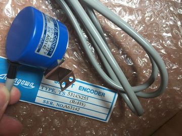
| Brand Name: | Tamagawa |
| Certification: | CE |
| Model Number: | TS5208N131 |
| Minimum Order Quantity: | 1pcs |
|---|---|
| Packaging Details: | carton |
| Delivery Time: | in stock |
| Payment Terms: | T/T, Western Union, MoneyGram |
| Supply Ability: | 100pcs/week |
| TAMAGAWA: | TAMAGAWA | Material: | Iron |
|---|---|---|---|
| Color: | Black | Japan: | Japan |
| TS5208N131: | TS5208N131 | Temperature: | 20-90 |
| Wire: | Wire | Dimension: | 80mm |
TS5208N131
| the CPU is in RUN mode. | Parity ? Data bits per character ? Number of stop bits ? Flow control (RS232 only) |
| The port settings revert to the device configuration settings after a STOP transition or power cycle. |
if configured. The "Properties" tab of the inspector window |
| After configuring the hardware devices (Page 119), you configure parameters for the communication interfaces by selecting one of the CMs in your rack or the CB, |
displays the parameters of the selected CM or CB. Select "Port configuration" to edit the following parameters: ? Baud rate |
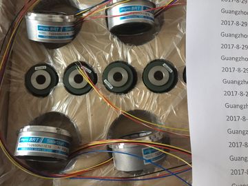
Guang Zhou Lai Jie Electric Co.,LTD
Please contact with “Tommy” for the price
TS5208N530
TS5208N569
TS5208N576
TS5210N450
TS5210N453
TS5210N458
TS5210N530
TS5210N54
TS5210N553
TS3684N1E3
TS3684N2E6
TS3684N3E8
TS3684N11E3
TS3684N12E6
TS3684N13E8
TS3617N1E3
TS3617N1E1
TS3617N1E2
TS3617N2E4
TS3617N2E5
TS3617N2E6
TS3617N2E7
TS3617N3E8
TS3617N3E9
TS3617N3E1
TS3617N11E3
TS3617N11E1
TS3617N11E2
TS3617N12E4
TS3617N12E5
TS3617N12E6
TS3617N12E7
TS3617N13E8
TS3617N13E9
TS3617N13E1
TS3653N1E1
Wait time
For the CM 1241 RS232 and RS485 and CB RS485 (except for flow control, which only the
CM 1241 RS232 supports), the port configuration parameters are the same regardless of
whether you are configuring an RS232 or an RS485 communication module or the RS485
communication board. The parameter values can differ.
For the CM 1241 RS422/485, the Port configuration is performed differently as shown in the
figure below. The 422 mode of the CM 1241 RS422/485 module supports software flow
control as well. Select "Port configuration" to edit the following
RS422/485 parameters:
? "Operating mode":
– Full duplex (RS422) four wire mode (point-topoint
connection)
– Full duplex (RS422) four wire mode (multipoint
master)
– Full duplex (RS422) four wire mode (multipoint
slave)
– Half duplex (RS485) two wire mode
? "Receive line initial state":
– None
– Forward bias (Signal R(A) 0V, signal R(B) 5V)
The STEP 7 user program can also configure the port or change the existing configuration
with the PORT_CFG instruction (Page 568).
Note
Parameter values set from the PORT_CFG instruction in the user program override port
configuration settings set from the device configuration. Note that the does not
retain parameters set from the PORT_CFG instruction in the event of power downThe default value for the baud rate is 9.6 Kbits per second. Valid choices are: 300 baud,
600 baud, 1.2 Kbits, 2.4 Kbits, 4.8 Kbits, 9.6 Kbits, 19.2 Kbits, 38.4 Kbits, 57.6 Kbits, 76.8
Kbits, and 115.2 Kbits.
Parity The default value for parity is no parity. Valid choices are: No parity, even, odd, mark (parity
bit always set to 1), and space (parity bit always set to 0).
Data bits per character The number of data bits in a character. Valid choices are 7 or 8.
Number of stop bits The number of stop bits can be either one or two. The default is one.
Flow control For the RS232 communication module, you can select either hardware or software flow
control, as described in the section "Managing flow control (Page 585)". If you select
hardware flow control, you can select whether the RTS signal is always on, or RTS is
switched. If you select software flow control, you can define the XON and XOFF characters.
The RS485 communication interfaces do not support flow control. The 422 mode of the CM
1241 RS422/485 module supports software flow control.
Wait time Wait time specifies the time that the CM or CB waits to receive CTS after asserting RTS, or
for receiving an XON after receiving an XOFF, depending on the type of flow control. If the
wait time expires before the communication interface receives an expected CTS or XON,
the CM or CB aborts the transmit operation and returns an error to the user program. You
specify the wait time in milliseconds. The range is 0 to 65535 milliseconds.
Operating mode This selects the operating mode RS422 or RS485 and network configurations.
Receive line initial state This selects the bias options. Valid values are none, forward bias and reverse bias.
Reverse bias is used to allow cable break detection. Flow control refers to a mechanism for balancing the sending and receiving of data
transmissions so that no data is lost. Flow control ensures that a transmitting device is not
sending more information than a receiving device can handle. Flow control can be
accomplished through either hardware or software. The RS232 CM supports both hardware
and software flow control. The RS485 CM and CB do not support flow control. The 422
mode of the CM 1241 RS422/485 module supports software flow control. You specify the
type of flow control either when you configure the port (Page 583) or with the PORT_CFG
instruction (Page 568).
Hardware flow control works through the Request-to-send (RTS) and Clear-to-send (CTS)
communication signals. With the RS232 CM, the RTS signal is output from pin 7 and the
CTS signal is received through pin 8. The RS232 CM is a DTE (Data Terminal Equipment)
device which asserts RTS as an output and monitors CTS as an input.If you enable RTS switched hardware flow control for an RS232 CM, the module sets the
RTS signal active to send data. It monitors the CTS signal to determine whether the
receiving device can accept data. When the CTS signal is active, the module can transmit
data as long as the CTS signal remains active. If the CTS signal goes inactive, then the
transmission must stop.
Transmission resumes when the CTS signal becomes active. If the CTS signal does not
become active within the configured wait time, the module aborts the transmission and
returns an error to the user program. You specify the wait time in the port configuration
(Page 583).
The RTS switched flow control is useful for devices that require a signal that the transmit is
active. An example would be a radio modem that uses RTS as a "Key" signal to energize the
radio transmitter. The RTS switched flow control will not function with standard telephone
modems. Use the RTS always on selection for telephone modems.In RTS always on mode, the CM 1241 sets RTS active by default. A device such as a
telephone modem monitors the RTS signal from the CM and utilizes this signal as a clear-tosend.
The modem only transmits to the CM when RTS is active, that is, when the telephone
modem sees an active CTS. If RTS is inactive, the telephone module does not transmit to
the CM.
To allow the modem to send data to the CM at any time, configure "RTS always on"
hardware flow control. The CM thus sets the RTS signal active all the time. The CM will not
set RTS inactive even if the module cannot accept characters. The transmitting device must
ensure that it does not overrun the receive buffer of the CM.
Data Terminal Block Ready (DTR) and Data Set Ready (DSR) signal utilization
The CM sets DTR active for either type of hardware flow control. The module transmits only
when the DSR signal becomes active. The state of DSR is only evaluated at the start of the
send operation. If DSR becomes inactive after transmission has started, the transmission will
not be paused. Software flow control uses special characters in the messages to provide flow control. You
configure Hex characters that represent XON and XOFF.
XOFF indicates that a transmission must stop. XON indicates that a transmission can
resume. XOFF and XON must not be the same character.
When the transmitting device receives an XOFF character from the receiving device, it stops
transmitting. Transmitting resumes when the transmitting device receives an XON character.