|
| Place of Origin: | Japan |
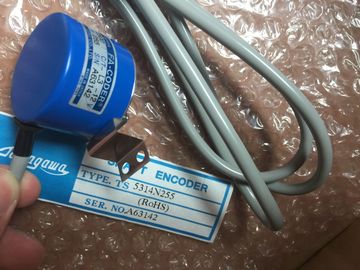
| Brand Name: | Tamagawa |
| Certification: | CE |
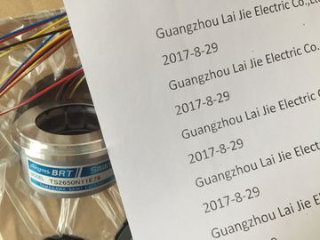
| Model Number: | TS5208N111E78 |
| Minimum Order Quantity: | 1pcs |
|---|---|
| Packaging Details: | carton |
| Delivery Time: | in stock |
| Payment Terms: | T/T, Western Union, MoneyGram |
| Supply Ability: | 100pcs/week |
| TAMAGAWA: | TAMAGAWA | TS5208N111E78: | TS5208N111E78 |
|---|---|---|---|
| Material: | Iron | Color: | Black |
| Japan: | Japan | Dimension: | 80mm |
| Temperature: | 20-90 | Wire: | Wire |
TS5208N111E78
| n: the character position (1-based) within the message that starts the length specifier | the length count |
| Length size: The number of bytes (one, two, or four) of the length specifier | The ending characters do not need to be contiguous. The "Length m" value can be used to specify the length of a checksum field whose size is not included in the length field. |
| Length m: the number of characters following the length specifier that are not included in | The ending characters do not need to be contiguous. The "Length m" value can be used to specify the length of a checksum field whose size is not included in the length field. |
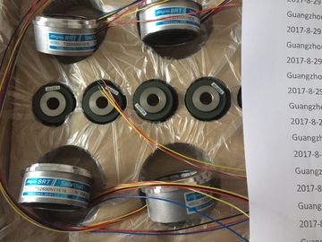
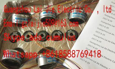
Guang Zhou Lai Jie Electric Co.,LTD
Please contact with “Tommy” for the price
TS1982N126E6
TS3653N44E8
TS3630N1E2
TS5013N89
TS2651N181E78
TS4127N1017E235
TS1982N128E6
8001231S
TS3653N4E12
TS5013N64
TS3630N2E3
TS5016N
TS5000N532
TS4231N6E17
TS1982N53E6
800123-2R
TS3653N14E12
TS5420N60
TS3630N2E4
TS5016N60
TS5000N632
TS4231N6E17
TS1982N56E18
TS3653N58E5
TS5778N155
TS3630N3E5
TS5003N632
TS4244N10E24
TS1982N56E18
800123-R-F
TS3653N65E27
TS5208N23
TS3630N101E2
TS5017N56
TS5005N122
TS4244N3E24
TS1983N146E5
TS3653N81E27
Configure the receive message length parameters for this message as follows:
● n = 2 (The message length starts with byte 2.)
● Length size = 1 (The message length is defined in one byte.)
● Length m = 0 (There are no additional characters following the length specifier that are
not counted in the length count. Twelve characters follow the length specifier.)
In this example, the characters from 3 to 14 inclusive are the characters counted by Len (n).
Example 2: Consider another message structured according to the following protocolConfigure the receive message length parameters for this message as follows:
● n = 3 (The message length starts at byte 3.)
● Length size = 1 (The message length is defined in one byte.)
● Length m = 3 (There are three characters following the length specifier that are not
counted in the length. In the protocol of this example, the characters SD2, FCS, and ED
are not counted in the length count. The other six characters are counted in the length
count; therefore the total number of characters following the length specifier is nine.)
In this example, the characters from 5 to 10 inclusive are the characters counted by Len STEP 7 provides extended instructions that enable the user program to perform Point-toPoint
communications with a protocol designed and specified in the user program. These
instructions can be considered in two categories:
● Configuration instructions
● Communication instructions Before your user program can engage in PtP communication, you must configure the
communication interface port and the parameters for sending data and receiving data. Polling architecture
The point-to-point instructions must be called cyclically/periodically to check for
received messages. Polling the send will tell the user program when the transmit has
completed. The typical sequence for a master is as follows:
1. A SEND_PTP instruction initiates a transmission to the CM or CB.
2. The SEND_PTP instruction is executed on subsequent scans to poll for the transmit
complete status.
3. When the SEND_PTP instruction indicates that the transmission is complete, the user
code can prepare to receive the responseThe RCV_PTP instruction is executed repeatedly to check for a response. When the CM
or CB has collected a response message, the RCV_PTP instruction copies the response
to the CPU and indicates that new data has been received.
5. The user program can process the response.
6. Go to step 1 and repeat the cycle.
Polling architecture: slave
The typical sequence for a slave is as follows:
1. The user program executes the RCV_PTP instruction every scan.
2. When the CM or CB has received a request, the RCV_PTP instruction indicates that new
data is ready and the request is copied into the CPU.
3. The user program services the request and generates a response.
4. Use a SEND_PTP instruction to send the response back to the master.
5. Repeatedly execute SEND_PTP to be sure the transmit occurs.
6. Go to step 1 and repeat the cycle.
The slave must be responsible for calling RCV_PTP frequently enough to receive a
transmission from the master before the master times out while waiting for a response. To
accomplish this task, the user program can call RCV_PTP from a cyclic OB, where the cycle
time is sufficient to receive a transmission from the master before the timeout period expires.
If you set the cycle time for the OB to provide for two executions within the timeout period of
the master, the user program can receive transmissions without missing any.
12.3.5 Example: Point-to-Point communication
In this example, an CPU communicates to a PC with a terminal emulator through a
CM 1241 RS232 module. The point-to-point configuration and STEP 7 program in this
example illustrate how the CPU can receive a message from the PC and echo the message
back to the PC. You must connect the communication interface of the CM 1241 RS232 module to the RS232
interface of the PC, which is normally COM1. Because both of these ports are Data Terminal
Equipment (DTE), you must switch the receive and transmit pins (2 and 3) when connecting
the two ports, which you can accomplish by either of the following methods:
● Use a NULL modem adapter to swap pins 2 and 3 together with a standard RS232 cable.
● Use a NULL modem cable, which already has pins 2 and 3 swapped. You can usually
identify a NULL modem cable as one with two female 9-pin D connector ends.
12.3.5.1 Configuring the communication module
You can configure the CM 1241 from the Device configuration in STEP 7 or with user
program instructions. This example uses the Device configuration method.
● Port configuration: Click the communication port of the CM module from the Device
configuration, and configure the port as shown: