 |
| Place of Origin: | Japan |
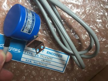
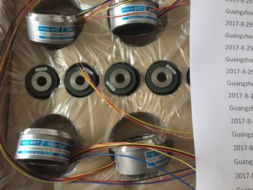
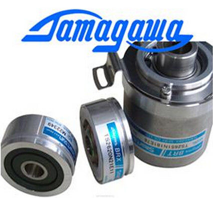
| Brand Name: | Tamagawa |
| Certification: | CE |
| Model Number: | TS2650N11E78 |
| Minimum Order Quantity: | 1pcs |
|---|---|
| Packaging Details: | carton |
| Delivery Time: | in stock |
| Payment Terms: | T/T, Western Union, MoneyGram |
| Supply Ability: | 100pcs/week |
| TAMAGAWA: | TAMAGAWA | TS2650N11E78: | TS2650N11E78 |
|---|---|---|---|
| Material: | Iron | Color: | Black |
| Japan: | Japan | Dimension: | 80mm |
| Temperature: | 20-90 | Wire: | Wire |
TS2650N11E78
| Network 1 "PortStatus" port status and "USS_DRV_DB".USS_Extended_Error extended error code values are only |
Error value in "LastExtError". |
| valid for one program scan. The values must be captured for later processing. |
SS drives support read and write access to a drive's internal paraers. This feature |
| etwork 2 The "PortError" contact triggers the storage of the "PortStatus" value in "LastPortStatus" |
allows remote control and configuration of the drive. |
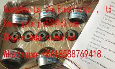
Guang Zhou Lai Jie Electric Co.,LTD
Please contact with “Tommy” for the price
TS3664N2E3
TS5013N60
TS3641N22E7
TS5208N68
TS5210N450
TS4503N1202E200
TS3103N178
TS3664N2E4
TS5013N61
TS3641N2E3
TS5212N351
TS5210N453
TS4503N1205E200
TS3103N255
TS3664N50
TS5016N60
TS3641N12E3
TS5212N510
TS5210N458
TS4503N1828E100
TS3103N302
OAH14BSD
TS3667N1E2
TS5013N63
TS3641N32
TS5213N550
TS5210N530
TS4503N2000E100
TS3103N40
OAS66
TS3667N11E2
TS5016N61
TS3641N38
TS5213N551
TS5210N54
TS4503N2070E100
TS3132N32
Drive paraer access operations can
fail due to errors such as values out of range or illegal requests for a drive's current mode.
The drive generates an error code value that is returned in the "USS_Extended_Error"
variable. This error code value is only valid for the last execution of a USS_RPM or
USS_WPM instruction. The drive error code is put into USS_Extended_Error variable when
the STATUS code value is hexadecimal 818C. The error code value of
"USS_Extended_Error" depends on the drive model. See the drive's manual for a description
of the extended error codes for read and write paraer operations.
● The drives must be set to use 4 PKW words.
● The drives can be configured for 2, 4, 6, or 8 PZD words.
● The number of PZD word's in the drive must match PZD_LEN input on the USS_DRV
instruction for that drive.
● The baud rate in all the drives must match the BAUD input on the USS_PORT instruction.
● The drive must be set for remote control.
● The drive must be set for frequency set-point to USS on COM Link.
● The drive address must be set to 1 to 16 and match the DRIVE input on the USS_DRV
block for that drive.
● The drive direction control must be set to use the polarity of the drive set-point.
● The RS485 network must be terminated properly. This information about MicroMaster drives is provided as an example. For other
drives, refer to the drive's manual for setup instructions.
To make the connection to a MicroMaster Series 4 (MM4) drive, insert the ends of the
RS485 cable into the two caged-clamp, screw-less terminals provided for USS operation.
Standard PROFIBUS cable and connectors can be used to connect the These unwanted currents can cause communications errors or damage equipment. Be sure
all equipment that you are about to connect with a communications cable either shares a
common circuit reference or is isolated to prevent unwanted current flows. The shield must
be tied to chassis ground or pin 1 on the 9-pin connector. It is recommended that you tie
wiring terminal 2--0V on the MicroMaster drive to chassis ground. The two wires at the opposite end of
the RS485 cable must be inserted into
the MM4 drive terminal blocks. To
make the cable connection on a MM4
drive, remove the drive cover(s) to
access the terminal blocks. See the
MM4 user manual for details about
how to remove the covers(s) of your
specific drive. The terminal block connections are labeled numerically. Using a PROFIBUS connector on
the side, connect the A terminal of the cable to the drive terminal 15 (for an MM420)
or terminal 30 (MM440). Connect the B terminal of B (P) A (N) the cable connector to
terminal 14 (MM420) or terminal 29 (MM440).
If the is a terminating node in the network, or if the connection is point-to-point, it is
necessary to use terminals A1 and B1 (not A2 and B2) of the connector since they allow the
termination settings to be set (for example, with DP connector type 6ES7 972--0BA40--
0X40). If the drive is configured as the terminating
node in the network, then termination and
bias resistors must also be wired to the
appropriate terminal connections. This
diagram shows examples of the MM4 drive
connections necessary for termination and
bias.Before you connect a drive to the , you must ensure that the drive has the following
system paraers. Use the keypad on the drive to set the paraers:
Reset the drive to factory settings (optional). P0010=30
P0970=1
If you skip step 1, then ensure that these paraers are set to the indicated
values.
USS PZD length = P2012 Index 0=(2, 4, 6,
or 8)
USS PKW length = P2013 Index 0=4
2. Enable the read/write access to all paraers (Expert mode). P0003=3
3. Check the motor settings for your drive. The settings will vary according to
the motor(s) being used.
To set the paraers P304, P305, P307, P310, and P311, you must first set
paraer P010 to 1 (quick commissioning mode). When you are finished
setting the paraers, set paraer P010 to 0. Paraers P304, P305,
P307, P310, and P311 can only be changed in the quick commissioning
mode.
P0304 = Rated motor voltage (V)
P0305 = Rated motor current (A)
P0307 = Rated motor power (W)
P03010 = Rated motor frequency (Hz)
P0311 = Rated motor speed
4. Set the local/remote control mode. P0700 Index 0=5
5. Set selection of frequency set-point to USS on COM link. P1000 Index 0=5
6. Ramp up time (optional)
This is the time in seconds that it takes the motor to accelerate to maximum