 |
| Place of Origin: | Japan |
| Brand Name: | Tamagawa |
| Certification: | CE |
| Model Number: | TS2014N312E32 |
| Minimum Order Quantity: | 1pcs |
|---|---|
| Packaging Details: | carton |
| Delivery Time: | in stock |
| Payment Terms: | T/T, Western Union, MoneyGram |
| Supply Ability: | 100pcs/week |
| TAMAGAWA: | TAMAGAWA | Material: | Iron |
|---|---|---|---|
| Color: | Black | Japan: | Japan |
| Temperature: | 20-90 | Dimension: | 60mm |
| Wire: | Wire | TS2014N312E32: | TS2014N312E32 |
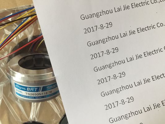
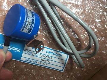
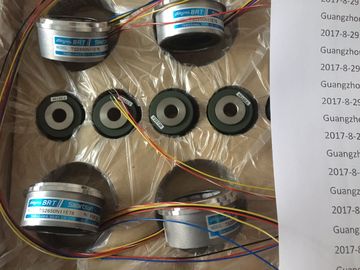
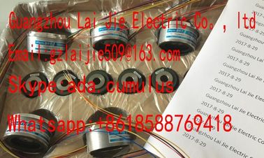
TS2014N312E32
Guang Zhou Lai Jie Electric Co.,LTD
Please contact with “Tommy” for the price
TS5013N60
TS5013N61
TS5016N60
TS5013N63
TS5013N64
TS5016N61
TS5013N66
TS5016N63
TS5016N64
TS5017N60
TS5019N60
TS5420N60
TS5778N155
TS5013N68
TS5013N69
TS5208N131
TS5208N23
TS2025N471E69
TS2014N181E32
TS5208N111E78
TS5208N141E78
TS5631N224
PULSE
GENERATOR
RP-182
750PPR
PULSE
GENERATOR
RP-182
1500PPR
PULSE
![]()
![]()
![]()
![]()
| The USS instructions control the operation of motor drives which support the universal serial interface (USS) protocol | The USS protocol uses a master-slave network for communications over a serial bus. The master uses an address parameter to send a message to a selected slave. |
| Up to three CM 1241 RS422/RS485 modules and one CB 1241 RS485 board can be installed in a S7-1200 CPU. Each RS485 port can operate up to sixteen drives. | . A slave itself can never transmit without first receiving a request to do so. |
| You can use the USS instructions to communicate with multiple drives through RS485 connections to CM 1241 RS485 communication modules or a CB 1241 RS485 communication board. | Direct message transfer between the individual slaves is not possible. USS communication operates in half-duplex mode. The following USS illustration shows a network diagram for an example drive application. |
The four USS instructions use 1 FB and 3 FCs to support the USS protocol. One USS_PORT instance data block (DB) is used for each USS network. The USS_PORT instance data block contains temporary storage and buffers for all drives on that USS network. The USS instructions share the information in this data block. The four USS instructions use 1 FB and 3 FCs to support the USS protocol. One USS_PORT instance data block (DB) is used for each USS network. The USS_PORT instance data block contains temporary storage and buffers for all drives on that USS network. The USS instructions share the information in this data block.
The USS_PORT function handles the actual communication between the CPU and the drives via the Point-to-Point (PtP) RS485 communication port. Each call to this function handles one communication with one drive. Your program must call this function fast enough to prevent a communication timeout by the drives. You may call this function in a main program cycle OB or any interrupt OB. Typically, you should call the USS_PORT function from a cyclic interrupt OB. The cycle time of the cyclic interrupt OB should be set to about half of the minimum call interval (As an example, 1200 baud communication should use a cyclic time of 350 ms or less). The USS_DRV function block provides your program access to a specified drive on the USS network. Its inputs and outputs are the status and controls for the drive. If there are 16 drives on the network, your program must have at least 16 USS_DRV calls, one for each drive. These blocks should be called at the rate that is required to control the operation of the drive. You may only call the USS_DRV function block from a main program cycle OBOnly call USS_DRV, USS_RPM, and USS_WPM from a main program cycle OB. The USS_PORT function can be called from any OB, usually from a cyclic interrupt OB. Do not use instructions USS_DRV, USS_RPM, or USS_WPM in a higher priority OB than the corresponding USS_PORT instruction. For example, do not place the USS_PORT in the main and a USS_RPM in a cyclic interrupt OB. Failure to prevent interruption of USS_PORT execution may produce unexpected errors. The USS_RPM and USS_WPM functions read and write the remote drive operating parameters. These parameters control the internal operation of the drive. See the drive manual for the definition of these parameters. Your program can contain as many of these functions as necessary, but only one read or write request can be active per drive, at any given time. You may only call the USS_RPM and USS_WPM functions from a main program cycle OB.