 |
| Place of Origin: | Japan |
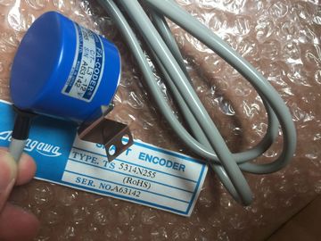
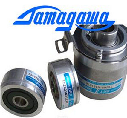
| Brand Name: | Tamagawa |
| Certification: | CE |
| Model Number: | TS2014N43E31 |
| Minimum Order Quantity: | 1pcs |
|---|---|
| Packaging Details: | carton |
| Delivery Time: | in stock |
| Payment Terms: | T/T, Western Union, MoneyGram |
| Supply Ability: | 100pcs/week |
| TAMAGAWA: | TAMAGAWA | Material: | Iron |
|---|---|---|---|
| Japan: | Japan | Color: | Black |
| TS2014N43E31: | TS2014N43E31 | Wire: | Wire |
| Dimension: | 70mm | Temperature: | 20-90 |
TS2014N43E31
| Communications with the drive are asynchronous to the S7-1200 scan cycle. | The table below shows the minimum USS_PORT interval for each communication baud rate. C |
| The S7-1200 typically completes several scans before one drive communications transaction is completed. | Calling the USS_PORT function more frequently than the USS_PORT interval will not increase the number of transactions |
| The USS_PORT interval is the time required for one drive transaction | . The drive timeout interval is the amount of time that might be taken for a transaction, |
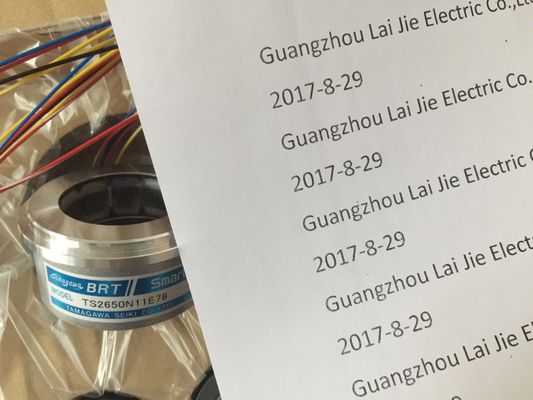
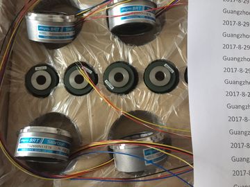
Guang Zhou Lai Jie Electric Co.,LTD
Please contact with “Tommy” for the price
TS3641N22E7
TS3641N2E3
TS3641N12E3
TS3641N32
TS3641N38
TS3643N2
TS3643N212E5
TS3643N233E8
TS3653N11E2
TS3653N12E5
TS3653N13E8
TS3653N1E1
TS3653N1E2
TS3653N2E4
TS3653N2E5
TS3653N2E6
TS3653N3E7
TS3653N3E8
TS3653N3E9
TS3653N13E9
TS3653N44E8
TS3653N4E12
TS3653N14E12
TS3653N58E5
TS3653N65E27
TS3653N81E27
TS3653N78E5
TS3653N94E5
TS3653N181E8
TS3658N3
TS3664N1E1
TS3664N1E2
TS3664N2E3
TS3664N2E4
TS3664N50
TS3664N50
TS3667N1E2
TS3667N11E2
, if communications errors caused 3 tries to complete the transaction. By default, the USS protocol library automatically does up to 2 retries on each transactionThe USS_DRV instruction exchanges data with a drive by creating request messages and interpreting the drive response messages. A separate function block should be used for each drive, but all USS functions associated with one USS network and PtP communication port must use the same instance data block. You must create the DB name when you place the first USS_DRV instruction and then reference the DB that was created by the initial instruction usage. STEP 7 automatically creates the DB when you insert the instruction. Drive start bit: When true, this input enables the drive to run at the preset speed. When RUN goes to false while a drive is running, the motor will be ramped down to a stop. This behavior differs from the dropping power (OFF2) or braking the motor (OFF3). OFF2 IN Bool Electrical stop bit: When false, this bit cause the drive to coast to a stop with no braking. OFF3 IN Bool Fast stop bit: When false, this bit causes a fast stop by braking the drive rather than just allowing the drive to coast to a stop. LAD and FBD: Expand the box to reveal all the parameters by clicking the bottom of the box. The parameter pins that are grayed are optional and parameter assignment is not required.
Fault acknowledge bit: This bit is set to reset the fault bit on a drive. The bit is set after the fault is cleared to indicate to the drive it no longer needs to indicate the previous fault. DIR IN Bool Drive direction control: This bit is set to indicate that the direction is forward (for positive SPEED_SP). DRIVE IN USInt Drive address: This input is the address of the USS drive. The valid range is drive 1 to drive 16. PZD_LEN IN USInt Word length: This is the number of words of PZD data. The valid values are 2, 4, 6, or 8 words. The default value is 2. SPEED_SP IN Real Speed set point: This is the speed of the drive as a percentage of configured frequency. A positive value specifies forward direction (when DIR is true). Valid range is 200.00 to -200.00.
Drive direction: This bit indicates whether the drive is running forward. INHIBIT OUT Bool Drive inhibited: This bit indicates the state of the inhibit bit on the drive. FAULT OUT Bool Drive fault: This bit indicates that the drive has registered a fault. You must fix the problem and then set the F_ACK bit to clear this bit when set. SPEED OUT Real Drive Current Speed (scaled value of drive status word 2): The value of the speed of the drive as a percentage of configured speed. STATUS1 OUT Word Drive Status Word 1: This value contains fixed status bits of a drive. STATUS3 OUT Word Drive Status Word 3: This value contains a user-configurable status word on the drive. STATUS4 OUT Word Drive Status Word 4: This value contains a user-configurable status word on the drive. STATUS5 OUT Word Drive Status Word 5: This value contains a user-configurable status word on the drive.