|
| Place of Origin: | Japan |
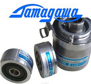
| Brand Name: | Tamagawa |
| Certification: | TS5016N60 |
| Model Number: | TS5016N60 |
| Minimum Order Quantity: | 1pcs |
|---|---|
| Packaging Details: | CARTON |
| Delivery Time: | IN STOCK |
| Payment Terms: | T/T, Western Union, MoneyGram |
| Supply Ability: | 100PCS/WEEK |
| TAMAGAWA: | TAMAGAWA | Material: | Iron |
|---|---|---|---|
| Color: | Black | Temperature: | 50-120 |
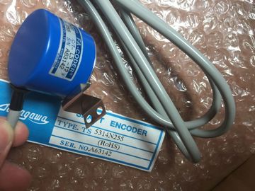
| Dimension: | 50mm | WIRE: | WIRE |
| TS5016N60: | TS5016N60 |
TS5016N60
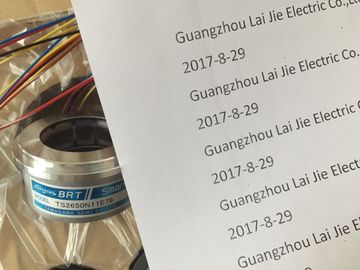
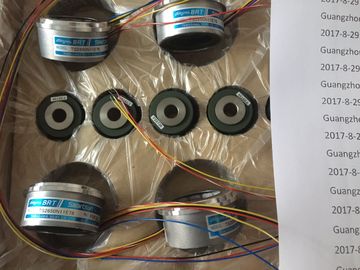
Guang Zhou Lai Jie Electric Co.,LTD
Please contact with “Tommy” for the price
TS3624N3E5
TS3624N3E6
TS3630N1303E9
TS3630N1309E5
TS3630N1306
TS3630N1E1
TS3630N1E2
TS3630N2E3
TS3630N2E4
TS3630N3E5
TS3630N101E2
TS3630N102E4
TS3630N22E3
TS3630N22E4
TS3631N1E1
TS3636N6
TS3641N1E1
TS3641N21E6
TS3641N22E7
TS3641N2E3
TS3641N12E3
TS3641N32
TS3641N38
TS3643N2
TS3643N212E5
TS3643N233E8
TS3653N11E2
TS3653N12E5
TS3653N13E8
![]()
![]()
![]()
![]()
| If a diagnostics was pending prior to reconfiguration, the SF LEDs (on CPU, IM or module) | |
| may be lit even though diagnostics are no longer pending and the module is operating correctly. |
|
| Only assign new parameters if no diagnostics is pending, |
unplug module and plug it in again.
The measurement type and range is configured at the "measuring range" parameter in
STEP 7.
The default setting of the module is "voltage" measurement with "± 10V" range. You can use
these default settings without having to program the SM 331; AI 8 x 16 Bit in STEP 7Enable
• Diagnostic interrupt
• Hardware interrupt when
limit exceeded
yes/no
yes/no
no
no
dynamic Module
Hardware interrupt trigger
• High limit
• Low limit
May be restricted by the measuring range.
from 32511 to - 32512
from - 32512 to 32511
- dynamic Channel
Diagnostics
• Group diagnostics
• with line continuity check
yes/no
yes/no
no
notatic Channel
groupMeasurement
Measurement type disabled
Voltage V:4DMU current (4-wire transducer)Vdynamic Channel
group • Measuring range See the table Measurement types and ranges ± 10 V• Noise suppression 100 Hz; 60 Hz; 50 Hz; 10 Hz 50 Hz
The channels of SM 331; AI 8 x 16 Bit are arranged in four groups of two channels. You can
assign parameters only to one channel group.The table below shows the relevant configuration of channel groups. The channel groupnumber is required to program SFC parameters in the user program.Table 6- 7 Assignment of SM 331; AI 8 x 16 Bit channels to channel groupsSet the "disabled" value at the "measuring type" parameter for unused channels. This setting
reduces module cycle times.As certain programmed inputs may remain unused due to the channel group configuration,
make allowances for the special features of those inputs outlined below in order to be able to
use the diagnostic functions at these used channels:● Measuring range 1 V to 5 V: wire the used input and unused input of the same channel
group in parallel.● Current measurement, 4 mA to 20 mA: wire the used input and unused input of the samechannel group in series. Connect a shunt resistor to each programmed and unused
channel.● Other measuring ranges:Short-circuit the plus and minus inputs of the channel.heck
The line continuity check is available for the 1 V to 5 V and 4 mA to 20 mA ranges.Rule for both measuring ranges:
When the line continuity check is enabled, the module logs the wire-break to diagnostics
data when the current drops below 3.6 mA (0.9 V.)
The module also triggers a diagnostic interrupt if this function is enabled in the program.A wire break can only be signaled by means of the lit SF LED and the diagnostic bytes must
be evaluated in the user program if diagnostic interrupts are disabled.When line continuity check is disabled and diagnostic interrupts are enabled, the moduletriggers a diagnostic interrupt when underflow is detected.n programming high and low limitsThe programmable limits (hardware interrupt triggers) of SM 331; AI 8 x 16 Bit differ from the
range of value shown in the Overview of parameters of SM 331; AI 8 x 16 Bit. table.
Reason: The calculation methods deployed in the module software to evaluate the processvariables do not allow the reporting of values up to 32511 in certain situations. The process
value triggering a hardware interrupt at underflow or overflow limits is based on thecalibration factors of the relevant channel, and may vary between the low limits shown in the
table below and the value 32511 (7EFFH).
You may not define any limits which exceed the minimum limits specified in the table below.Table 6- 8 Minimum high and low limits of SM 331; AI 8 x 16 BiSM 331; AI 8 x 16 Bit is capable of taking measurements, irrespective of the presence of anyCMV in the AC or DC range.
With AC CMV values of a multiple of filter frequency settings, noise is suppressed as a result
of ADC integration time and common mode suppression at the input amplifiers. With AC
CMV < 35 VRMS, the noise suppression of > 100 dB results in negligible measurement errors.
The influence of DC CMV can only be reduced to minimum using the noise suppression
function of the input amplifier unit. A certain degradation of measuring accuracy in proportion
to CMV must be expected. The worst case error is generated at 50 VDC between one
channel and the remaining seven channels. The calculated worst case error is 0.7% at 0 °C
to 60 °C, while the measured error usually lies at ≤ 0.1% at 25 °C.8 inputs in 4 channel groups
● Programmable measurement type at each channel group
– Voltage
– Current