 |
| Place of Origin: | Japan |
| Brand Name: | Tamagawa |
| Certification: | CE |
| Model Number: | TS5208N576 |
| Minimum Order Quantity: | 1pcs |
|---|---|
| Packaging Details: | carton |
| Delivery Time: | in stock |
| Payment Terms: | T/T, Western Union, MoneyGram |
| Supply Ability: | 100pcs/week |
| TAMAGAWA: | TAMAGAWA | COLOR: | BLACK |
|---|---|---|---|
| Material: | Iron | Temperature: | 40-120 |
| Wire: | Wire | TS5208N576: | TS5208N576 |
| Dimension: | 50mm |
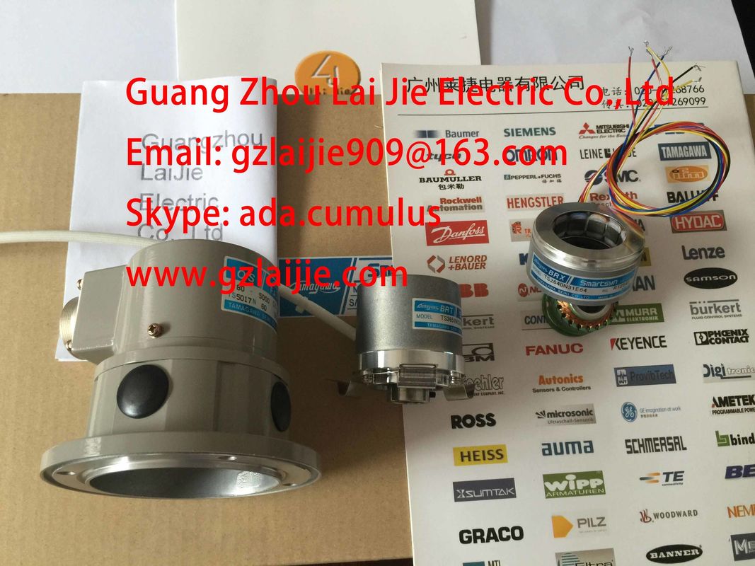
TS5208N576
Please contact with “Tommy” for the price
TS3103N255
TS3664N50
TS5016N60
TS3641N12E3
TS5212N510
TS5210N458
TS4503N1828E100
TS3103N302
OAH14BSD
TS3667N1E2
TS5013N63
TS3641N32
TS5213N550
TS5210N530
TS4503N2000E100
TS3103N40
OAS66
TS3667N11E2
TS5016N61
TS3641N38
TS5213N551
TS5210N54
TS4503N2070E100
TS3132N32
OAS66
TS1857N16EP
TS3667N2E5
TS5016N63
TS3643N2
TS5308N510
TS20E12
TS4503N2202E200
TS3134N21
![]()
![]()
![]()
| You can prevent the potential difference V ISO from exceeding limits by means of equipotential interconnection of terminals MANA and M of the CPU/IM153. |
Non-isolated analog input modules |
| Non-isolated analog input modules require a low-impedance connection between the | reference point of measuring circuit MANA and the M terminal of the CPU or interface module IM 153. |
| Interconnect terminals MANA with M of the CPU or interface module IM 153. Any |
potential difference between MANA and M of the CPU or interface module IM 153 may |
corrupt
the analog signal.
Limited potential difference CMV
The permissible potential difference UCM (CMV/Common Mode) may not be exceeded. A
CMV fault may develop between
● the measurement inputs (M+ / M-) and the reference potential of measuring circuit MANA
● between the measuring inputs.
The following diagrams show the measures to be taken when wiring transducers.
Electrically isolated transducers are not connected to local ground potential. They can be
operated in electrically isolated mode.
Potential differences may develop between electrically isolated sensors. These potential
differences may be caused by interference, or may develop as a result of the local
distribution of transducers.
In environments with a high level of EMC interference, it is advisable to interconnect M- with
MANA in order to prevent the permissible CMV value from being exceeded.Note
For modules where VCM ≤ 2.5 V, interconnect M- and MANA (see the diagrams below)
Do not interconnect M- with MANA when wiring and connecting 2-wire transducers andresistance transducers. An equalization current develops at the interconnection of M- withMANA and corrupts the measured value. This also applies to unused inputs which are
programmed accordingly.4.2.2 Wiring non-isolated transducersNon-isolated transducer
Non-isolated transducers are interconnected with local ground potential. Always interconnect
MANA with local ground when using non-isolated transducers.
Local conditions or interference may cause potential differences CMV (static or dynamic)between locally distributed measuring points. If the maximum CMV value is exceeded,interconnect the measuring points by means of equipotential conductorsWhen connecting non-isolated transducers to electrically isolated modules, the CPU / IM 153
can be operated in grounded or ungrounded mode.Always operate the CPU / IM 153 in grounded mode if you connect non-isolated transducersto non-isolated modules.You may not connect non-isolated 2-wire transducers/resistive transducers to non-isolated
analog inputs!This chapter describes how to wire and connect voltage transducers and and thecorresponding items to be observed.This chapter describes the wiring and connecting of current transducers and rules to beobserved.
Supported current transducers● As 2-wire transducer● As 4-wire transducernecting 2-wire transducers with power supply from the moduleThe 2-wire transducer is wired to the short circuit-proof supply voltage at the terminals of theanalog input module.
The 2-wire transducer converts the process variable into a current. 2-wire transducers must
be electrically isolated.
4-wire transducers are connected to a separately power supply
This chapter describes the wiring and connecting of resistance thermometers and resistors
and rules to be observed.