 |
| Place of Origin: | Japan |
| Brand Name: | Tamagawa |
| Certification: | CE |
| Model Number: | TS5210N453 |
| Minimum Order Quantity: | 1pcs |
|---|---|
| Packaging Details: | carton |
| Delivery Time: | in stock |
| Payment Terms: | T/T, Western Union, MoneyGram |
| Supply Ability: | 100pcs/week |
| TAMAGAWA: | TAMAGAWA | Material: | Iron |
|---|---|---|---|
| Color: | Black | Temperature: | 40-120 |
| TS5210N453: | TS5210N453 | Wire: | Wire |
| Dimension: | 40mm |
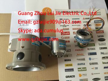
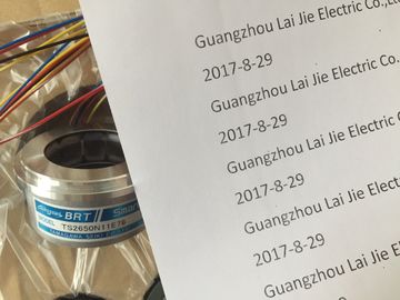
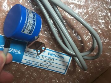
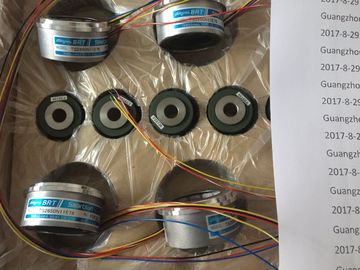
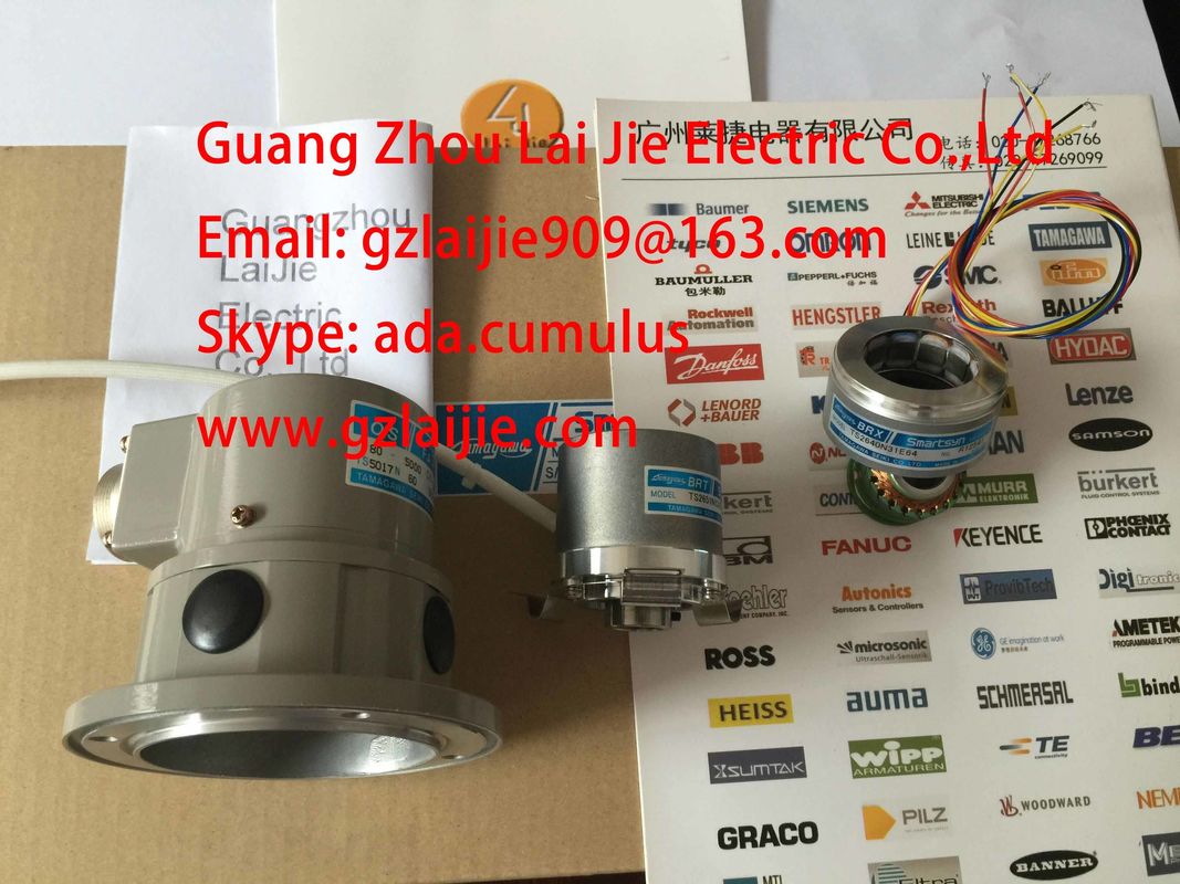
TS5210N453
Guang Zhou Lai Jie Electric Co.,LTD
Please contact with “Tommy” for the price
TS3134N52
OSE5K-6-12-108
TS3667N13E8
TS5013N68
TS3653N12E5
TS5320N632
TS2640N141E172
TS4507N1202E200
OSE5KN-6-12-108
TS3674N37
TS5013N69
TS3653N13E8
TS5420
TS2640N181E100
TS4507N1205E200
TS3166N43
TS3679N2E1
TS5208N131
TS3653N1E1
TS5641N150
TS2640N321E64
TS4507N1229E200
TS3212N32
RFH102422
TS3679N3E1
TS5208N111E78
TS3617N47E4
![]()
![]()
![]()
![]()
| Parameters set in STEP 7 may also be transferred to the module using SFCs 56 and 57 | |
| SFB 53 (refer to the STEP 7) Online Help). | |
| able 3- 38 Parameters of SM 327; |
Parameters Range of values
Default Parameter
type
Scope Data record
number
Programmable using ...
SFC55,
SFB53
PG
Digital output yes/no no dynamic Channel 1 yes yes
The readback function is a simple form of diagnostics. You can use this to determine
whether the information output to the process ("1" or "0") actually arrives there.
The digital outputs can be read back to the user data area: When Q11.3 is configured as an
output, for example, it can be read back at I11.3. See the figure below
his chapter describes the basic procedure in wiring and connecting signal sensors toanalog inputs and analog outputs and corresponding items to observe.
The diagrams below do not show the connecting lines required to connect the electricalpotentials of the analog input module and sensors.Always adhere to the general information on sensor wiring and connecting.Special wiring and connecting options are described in the corresponding module data.
Installation and wiring
For information on installation and wiring, refer to the , CPU 31xC, and
CPU 31x Operating Instructions: Installation The operating instructions are available on the
You can wire and connect the following transducers to the analog input modules, depending
on the type of measurement:
● Voltage transducers
● Current transducers
– As 2-wire transducer
– As 4-wire transducer
● Resistors
● Thermocouples
Cables for analog signals
Always use shielded twisted-pair cables to wire analog signals. This reduces interference.
Connect both ends of the analog cable shield to ground.
Any potential difference between the cable ends may cause an equipotential current on the
shield and disturbance on analog signals. Avoid this effect by means of low-impedance
equipotential bonding. Ground only one end of the shielding.
Electrically isolated analog input modules
Electrically isolated analog input modules are not electrically interconnected at the reference
point of the measuring circuit (MANA and/or M) and the M terminal of the CPU/IM153.
Always use electrically isolated analog input modules if there is any risk of potential
difference VISO developing between the reference point of measuring circuit (MANA and/or
M-) and the M terminal of the CPU/IM153 .