 |
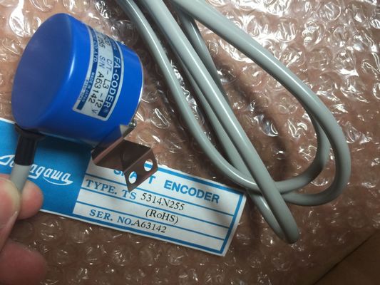
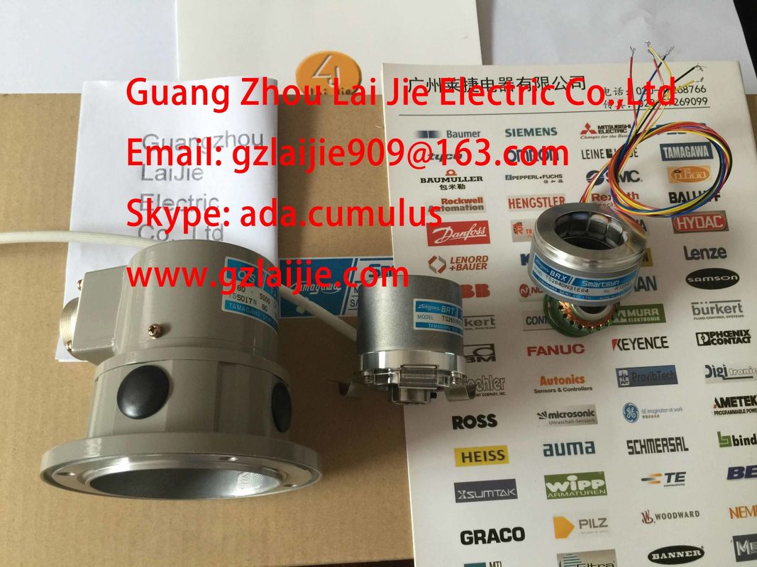
| Place of Origin: | Japan |
| Brand Name: | Tamagawa |
| Certification: | CE |
| Model Number: | TS5210N458 |
| Minimum Order Quantity: | 1pcs |
|---|---|
| Packaging Details: | carton |
| Delivery Time: | in stock |
| Payment Terms: | T/T, Western Union, MoneyGram |
| Supply Ability: | 100pcs/week |
| TAMAGAWA: | TAMAGAWA | TS5210N458: | TS5210N458 |
|---|---|---|---|
| Material: | Iron | Color: | Black |
| Temperature: | 30-120 | Wire: | Wire |
| Dimension: | 40mm |
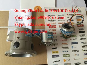
TS5210N458
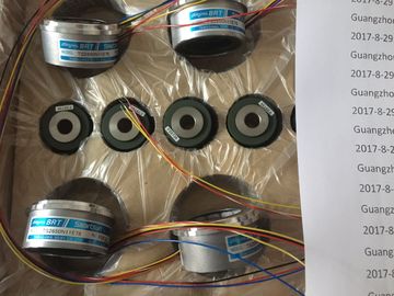
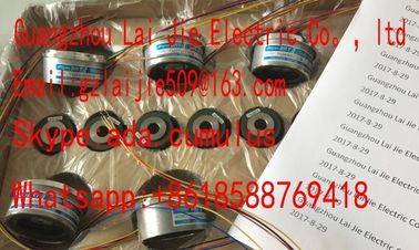
Guang Zhou Lai Jie Electric Co.,LTD
Please contact with “Tommy” for the price
TS3212N32
RFH102422
TS3679N3E1
TS5208N111E78
TS3617N47E4
TS1508N211
TS2650N11E78
TS4507N2000E100
TS3214N12
RFH1024-22-1M-68
TS3682N1
TS3617N1E1
TS3624N1E1
TS1508N255
TS2651N111E78
TS4507N2070E100
TS3214N13
RFH102422IM
TS3682N2
TS3617N1E2
TS3624N21E1
TS1508N257
TS26541N131E78
TS4507N2405E200
TS3214N15
TA8110N2121E802
TS3684N11E3
TS3617N2E4
TS3624N21E2
TS1508N260
TS3033N4E2
TS4507N6205E200
![]()
![]()
![]()
![]()
| Power failure at analog modules is always indicated by their relevant SF LED. | |
| Diagnostics interrupt triggering is based on parameter settings | |
| This information is also available on the module (in diagnostics buffer data.) |
Errors may lead to an entry in the diagnostics buffer and trigger a diagnostics interrupt atanalog modules with diagnostics function and corresponding parameter settings.
Influence of the range of values on the analog input moduleThe reaction of analog modules is determined by the actual input values within the range ofvaluesRated range Measured value - - -
Overshoot/undershootrange
Measured value - - -Overflow 7FFFH lit1 Entry is made1 Diagnostics interrupt1)Underflow 8000H lit1 Entry is made1 Diagnostics interrupt1)beyond programmed
limitMeasured value - - Process interrupt1)
1), only supported by modules with diagnostics function, and depending on parameter settingsThe reaction of analog modules is determined by the actual output values within the value
range.Table 5- 43 Reaction of analog output modules as a function of the actual analog value within the range of values
The operational limit represents the total measuring/output error of an analog module within
the permissible temperature range, based on the module's rating.
Basic error limit
The basic error limit represents the total measuring/output error at 25 °C, based on the
module's rating.
The percentile values of operational and basic error limits in the module's technical data
always refer to the highest possible input and output value within the nominal range of the
module.
Example of the determination of the output error of a module
An analog output module SM 332; AO 4 x 12 Bit is being used for voltage output. An output
range of "0 to 10 V" is set. The module is operating at an ambient temperature of 30 °C, i.e.
the operational limit applies. The technical data of the module state:
● Operational limit for voltage output: ±0,5 %
Hence, an output error of ±0.05 V (±0.5 % of 10 V) across the nominal range of the module
must be expected.
At an actual voltage of 1 V, for example, the module will then output a value in the range
from 0.95 V to 1.05 V. The relative error is ±5 % in this case.
For the example, the figure below shows how the relative error decreases as the output
value approaches the end of the 10-V range.
Figure 5-3 Example of the relative error of an analog output module
The conversion time is the total of the basic conversion time plus additional processing times
of the module for:
● Resistance measurement
● Wirebreak monitoring
The basic conversion time depends directly on the conversion method of the analog input
channel (integrating method, actual value conversion.)
The integration time of integrating conversions has a direct influence on conversion times.
The integration time depends on the interference frequency suppression you set in STEP 7.
For information on basic conversion times and additional processing times of the various
analog modules, refer to the technical data of the relevant module
Analog-to-digital conversion, and the transfer of digitized measured values to memory and/or
to the backplane bus, are carried out sequentially, i.e. the analog input channels are
converted in successive order. The cycle time, i.e. the time expiring until an analog input
value is converted again, represents the accumulated conversion time of all activated analoginput channels of the analog input module.
The figure below provides an overview of the cycle time elements for an n-channel analog
module.Make allowances for the accumulated channel conversion time when the analog input
channels are joined to form channel groups.wo analog input channels of the SM 331; AI 2 x 12 Bit analog input module form a channelgroup. You must therefore grade the cycle time in steps of 2.The measured values are smoothed by digital filtering. Smoothing is accomplished by themodule calculating mean values, derived from a defined number of converted (digitized)
analog values.
The user configures up to four grades of smoothing (none, low, average, high). The gradedetermines the number of analog signals used for averaging.