|
| Place of Origin: | Japan |
| Brand Name: | Tamagawa |
| Certification: | CE |
| Model Number: | TS2142N1E63 |
| Minimum Order Quantity: | 1pcs |
|---|---|
| Packaging Details: | carton |
| Delivery Time: | in stock |
| Payment Terms: | T/T, MoneyGram,Western Union |
| Supply Ability: | 100pcs/week |
| TAMAGAWA: | TAMAGAWA | TS2142N1E63: | TS2142N1E63 |
|---|---|---|---|
| Japan: | Japan | Material: | Iron |
| Color: | Black | Temperature: | 20-90 |
| Wire: | Wire | Dimension: | 50mm |
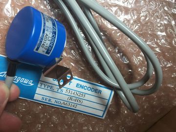
TS2142N1E63
| The serial communication interfaces have the following characteristics: ● Have an isolated port |
Display transmit and receive activity by means of LEDs ● Display a diagnostic LED (CMs only) |
| Are configured and programmed through extended instructions and library functions | Are powered by the CPU: No external power connection is needed. |
| Support Point-to-Point protocols | Refer to the technical specifications for communication interfacesThe communication |
Guang Zhou Lai Jie Electric Co.,LTD
Please contact with “Tommy” for the price
TS4603N1700E200
TS2087N12E9
TS2142N1E63
TS3617N381
TS4514N2002E200
TS3617N1E1
TS1922N3
TS4603N2002E200
TS2097N1E9
TS2151N1E26
TS3617N3E9
TS4514N2405E200
TS3617N1E2
TS2014N181E32
TS4603N7002E200
TS4602N6321E100
TS3617N2E4
TS3617N13E9
TS4515N1202E200
TS3617N11E1
TS2014N182E32
TS1505N55
TS4515N6000E200
TS4603N1000E100
TS3617N2E5
TS3617N40E3
TS4515N2405E200
TS3617N1E3
TS2014N185E32
TS4602N1000E200
TS4603N1000E200
TS3617N2E6
TS5214N566
TS5205N450
TS5213N551
TS5208N122
TS5208N23
TS5778N171
TS5210N53
TS5320N510
TS5000N632
TS5212N510
modules have three LED indicators:
● Diagnostic LED (DIAG): This LED flashes red until it is addressed by the CPU. After the
CPU powers up, it checks for CMs and addresses them. The diagnostic LED begins to
flash green. This means that the CPU has addressed the CM, but has not yet provided
the configuration to it. The CPU downloads the configuration to the configured CMs when
the program is downloaded to the CPU. After a download to the CPU, the diagnostic LED
on the communication module should be a steady green.
● Transmit LED (Tx): The transmit LED illuminates when data is being transmitted out the
communication port.
● Receive LED (Rx): This LED illuminates when data is being received by the
communication port.
The communication board provides transmit (TxD) and receive (RxD) LEDs. It has no
diagnostic LED. provides an RS485 network connector (Page 834) that you can use to easily
connect multiple devices to an RS485 network. The connector has two sets of terminals that
allow you to attach the incoming and outgoing network cables. The connector also includes
switches for selectively biasing and terminating the network.
Note
You terminate and bias only the two ends of the RS485 network. The devices in between the
two end devices are not terminated or biased. Bare cable shielding: Approximately 12 mm
(1/2 in) must contact the metal guides of all locations.Switch position = On: Terminated and biased
② Switch position = Off: No termination or bias
③ Switch position = On: Terminated and biasedSwitch position = On: Terminated and biased
② Switch position = Off: No termination or bias
③ Switch position = On: Terminated and biasedThe CPU supports the following Point-to-Point communication (PtP) for character-based![]()
![]()
serial protocols. PtP provides maximum freedom and flexibility, but requires extensive
implementation in the user program.
The CPU supports the following Point-to-Point communication (PtP) for character-based
serial protocols. PtP provides maximum freedom and flexibility, but requires extensive
implementation in the user program.
Many of the PtP instructions use the REQ input to initiate the operation on a low to high
transition. The REQ input must be high (TRUE) for one execution of an instruction, but the REQ
input can remain TRUE for as long as desired. The instruction does not initiate another operation
until it has been called with the REQ input FALSE so that the instruction can reset the history
state of the REQ input. This is required so that the instruction can detect the low to high transition
to initiate the next operation.
When you place a PtP instruction in your program, STEP 7 prompts you to identify the instance
DB. Use a unique DB for each PtP instruction call. This ensures that each instruction properly
handles inputs such as REQ.
PORT A port address is assigned during communication device configuration. After configuration, a
default port symbolic name can be selected from the parameter assistant drop-list. The assigned
CM or CB port value is the device configuration property "hardware identifier". The port symbolic
name is assigned in the "Constants" tab of the PLC tag table.
Bit time resolution Several parameters are specified in a number of bit times at the configured baud rate. Specifying
the parameter in bit times allows the parameter to be independent of baud rate. All parameters
that are in units of bit times can be specified to a maximum number of 65535. However, the
maximum amount of time that a CM or CB can measure is eight seconds.
The DONE, NDR, ERROR, and STATUS output parameters of the PtP instructions provide
execution completion status for the PtP operations. Set TRUE for one execution to indicate that the last request
completed without errors; otherwise, FALSE.
NDR Bool FALSE Set TRUE for one execution to indicate that the requested action
has completed without error and that the new data has been
received; otherwise, FALSE.
ERROR Bool FALSE Set TRUE for one execution to indicate that the last request
completed with errors, with the applicable error code in STATUS;
otherwise, FALSE.
STATUS Word 0 Result status:
If the DONE or NDR bit is set, then STATUS is set to 0 or to an
informational code.
If the ERROR bit is set, then STATUS is set to an error code.
If none of the above bits are set, then the instruction returns
status results that describe the current state of the function