 |
| Place of Origin: | Japan |
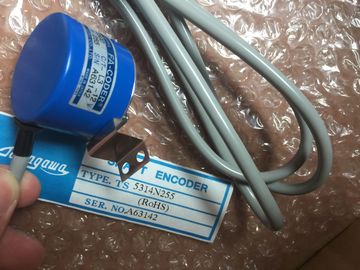
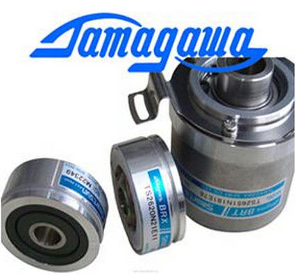
| Brand Name: | Tamagawa |
| Certification: | CE |
| Model Number: | TS2640N671E110 |
| Minimum Order Quantity: | 1pcs |
|---|---|
| Packaging Details: | carton |
| Delivery Time: | in stock |
| Payment Terms: | T/T, Western Union, MoneyGram |
| TAMAGAWA: | TAMAGAWA | Material: | Iron |
|---|---|---|---|
| Color: | Iron | Temperature: | 50-120 |
| Dimension: | 50mm | TS2640N671E110: | TS2640N671E110 |
| Wire: | Wire |
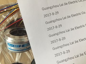
TS2640N671E110
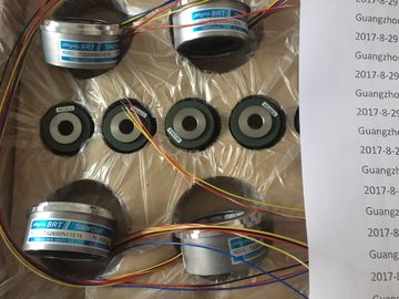
Guang Zhou Lai Jie Electric Co.,LTD
Please contact with “Tommy” for the price
TS5778N157
TS3624N3E5
TS4886N9079E411
TS2640N321E64
TS3738N1E7
TS1980N56E12
60798024
TS3653N2E6
TS5787N10
TS3624N3E6
TS-5008-N-65
TS2641N31E64
TS3741N3E8
TS1981N134E9
610568-1A
TS3653N3E7
TS5850N60
TS3630N1303E9
TS5008N66
TS2650N1E78
TS374
TS1981N53E19
61347
TS3653N3E8
TS5850N64
TS3630N1309E5
TS5010N
TS2650N11E78
TS3762N15E4
TS1981N56E19
TS3653N3E9
TS5850N70
TS3630N1306
TS5013N69
TS2650N101E78
TS4126N1017E235
TS1981N56E19
TS3653N13E9
TS5N2E18
TS3630N1E1
TS5013N61
TS2651N111E78
TS4127N1017E215
TS1982N126E6
TS3653N44E8
TS3630N1E2
TS5013N89
TS2651N181E78
TS4127N1017E235
TS1982N128E6
8001231S
TS3653N4E12
TS5013N64
TS3630N2E3
TS5016N
TS5000N532
TS4231N6E17
TS1982N53E6
800123-2R
TS3653N14E12
TS5420N60
TS3630N2E4
TS5016N60
TS5000N632
TS4231N6E17
TS1982N56E18
TS3653N58E5
TS5778N155
TS3630N3E5
TS5003N632
TS4244N10E24
TS1982N56E18
800123-R-F
TS3653N65E27
TS5208N23
TS3630N101E2
TS5017N56
TS5005N122?
TS4244N3E24
TS1983N146E5
![]()
![]()
![]()
| programmable | |
| Types E, N, J, K, L | |
| Pt 100 (Standard and Klima range) Ni 100 (Standard and Klima range) Temperature compensation |
Internal temperature compensation
• External temperature compensation with compensating
box
• Compensation for 0 °C reference junction temperature
• Technical unit of temperature measurement
programmable
supported
supported
supported
degrees Centigrade
SM 331; AI 2 x 12 Bit is equipped with a measuring range module. The measurement type
and range is configured at the "measuring range" parameter in STEP 7. You can use the
default "voltage" measurement type and "± 10 V range without having to program the
SM 331; AI 2 x 12 Bit in STEP 7.
Measuring range module
Change the position of the measuring range module to set the measurement type and range
(see the chapter Setting the measurement types and ranges of analog input channels ). The
necessary settings are also available on the module's imprint. Mark the position of the
measuring range module on the front door (see figure).
Table 6- 21 Measurement types and ranges
The two channels of SM 331; AI 2 x 12 Bit form a channel group. You can assign parameters
only to one channel group.
SM 331; AI 2 x 12 Bit is equipped with a measuring range module for channel group 0.
Line continuity check
The line continuity check is designed only for temperature measurements (thermocouples
and thermoresistors.)
Special features of the line continuity check for the 4 mA to 20 mA measuring range
If you configured a measuring range of 4 mA to 20 mA, and enabled the line continuity
check, the analog input module logs a wire-break event to diagnostics data when the current
drops below 3.6 mA.
The module also triggers a diagnostics interrupt if this function is enabled in the program.
A wire break can only be signaled by means of the lit SF LED and the diagnostic bytes must
be evaluated in the user program if diagnostics interrupts are disabled.
If you configured a measuring range of 4 mA to 20 mA, disabled the line continuity check,
and enabled diagnostic interrupts, the module triggers a diagnostic interrupt when the
underflow value is reached.
For general information on programming analog modules, refer to the chapter Programming
analog modules (Page 294
Short-circuit unused channels and connect these with MANA. This optimizes interference
immunity of the analog input module. Set the "disabled" value at the "measurement type"
parameter for unused channels. This setting reduces module cycle times.
Also short-circuit the COMP input if this is not used.
As certain programmed inputs may remain unused due to the channel group configuration,
make allowances for the special features of these inputs outlined below in order to be able to
use the diagnostics functions at these used channels:
● Measuring range 1 V to 5 V: wire the used input and unused input of the same channel
group in parallel.
● Current measurement, 2-wire transducer: There are two options of setting up the channel
circuit:
a) Open unused input; channel group diagnostics disabled. The analog module would
trigger a single diagnostics interrupt and set its SF LED if diagnostics is enabled.
b) Terminating the unused input using a 1.5 kΩ to 3.3 kΩ resistor. This allows you to
enable diagnostics for this channel group.
● Current measurement 4 mA to 20 mA, 4-wire transducer: wire the used input and unused
input of the same cha
Line continuity check
The line continuity check is designed only for temperature measurements (thermocouples
and thermoresistors.)
Special features of the line continuity check for the 4 mA to 20 mA measuring range
If you configured a measuring range of 4 mA to 20 mA, and enabled the line continuity
check, the analog input module logs a wire-break event to diagnostics data when the current
drops below 3.6 mA.
The module also triggers a diagnostics interrupt if this function is enabled in the program.
A wire break can only be signaled by means of the lit SF LED and the diagnostic bytes must
be evaluated in the user program if diagnostics interrupts are disabled.
If you configured a measuring range of 4 mA to 20 mA, disabled the line continuity check
and enabled diagnostic interrupts, the module triggers a diagnostic interrupt when the
underflow value is reached.