 |
| Place of Origin: | Japan |
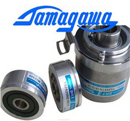
| Brand Name: | Tamagawa |
| Certification: | CE |
| Model Number: | TS2605N1E64 |
| Minimum Order Quantity: | 1pcs |
|---|---|
| Packaging Details: | carton |
| Delivery Time: | in stock |
| Payment Terms: | T/T, Western Union, MoneyGram |
| Supply Ability: | 100pcs/week |
| TAMAGAWA: | TAMAGAWA | TS2605N1E64: | TS2605N1E64 |
|---|---|---|---|
| Material: | Iron | Color: | Black |
| Temperature: | 40-120 | Dimension: | 50mm |
| Wire: | Wire |
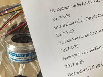
TS2605N1E64
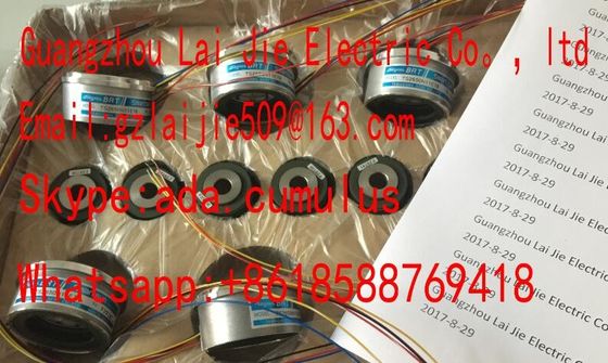
Guang Zhou Lai Jie Electric Co.,LTD
Please contact with “Tommy” for the price
TS3630N3E5
TS5003N632
TS4244N10E24
TS1982N56E18
800123-R-F
TS3653N65E27
TS5208N23
TS3630N101E2
TS5017N56
TS5005N122?
TS4244N3E24
TS1983N146E5
TS3653N81E27
TS2025N471E69
TS3630N102E4
TS5017N60
TS5007N122
TS4502N1000E200
TS1983N146E5
TS3653N78E5
TS2014N181E32
TS3630N22E3
TS5108-N153-5V
TS5007N635
TS4502N1202E200
TS252N30E1
AU6270N103E63
TS3653N94E5
TS5208N141E78
TS3630N22E4
TS5146N10
TS5208N500
TS4502N2000E100
TS3503N11E43
TS3653N181E8
TS3684N1E3
TS3631N1E1
TS5146N11
TS5208N510
TS4503N1000E200
TS3062E3
TS3658N3
TS3684N13E8
TS3636N6
TS-5170-N20
TS5208N530
TS4503N1007E200
TS3092N11E12
AU6550N2062
TS3664N1E1
TS3617N1E3
TS3641N1E1
TS5207N530
TS5208N569
TS4503N1022E100
TS3095N2
AU6649N2101
TS3664N1E2
TS3630N1214E3
TS3641N21E6
TS5208N510
TS5208N576
TS4503N1022E200
TS3103N156
FACODER
TS3664N2E3
TS5013N60
TS3641N22E7
TS5208N68
TS5210N450
TS4503N1202E200
TS3103N178
TS3664N2E4
TS5013N61
TS3641N2E3
TS5212N351
TS5210N453
TS4503N1205E200
| Loading the unused input using a 1. | |
| kΩ to 3.3 kΩ resistor. This allows you to enable diagnostics for this channel group. |
|
| Current measurement 4 mA to 20 mA, 4-wire transducer: wire the unused inputs of the same channel group in series |
If you disable all input channels of the module and enable diagnostics at the parameters of
SM 331; AI 8 x 12 Bit, the module does not report "external auxiliary voltage missing."
Line continuity check for the 4 mA to 20 mA measuring range
If you configured a measuring range of 4 mA to 20 mA, and enabled the line continuity
check, the analog input module logs a wire-break event to diagnostics data when the current
drops below 3.6 mA.
The module also triggers a diagnostics interrupt if this function is enabled in the program.
A wire break can only be signaled by means of the lit SF LED and the diagnostic bytes must
be evaluated in the user program if diagnostics interrupts are disabled.
If you configured a measuring range of 4 mA to 20 mA, disabled the line continuity check,
and enabled diagnostic interrupts, the module triggers a diagnostic interrupt when the
underflow value is reached.
The line continuity check is designed only for temperature measurements (thermocouples
and thermoresistors.)
See also
Representation of the values for analog input channels
Two inputs in one channel group
● Programmable measurement type for each channel group
– Voltage
– Current
– Resistance
– Temperature
● Programmable resolution at each channel group (9/12/14 bits + sign)
● Any measuring range selection per channel group
● Programmable diagnostics and diagnostic interrupt
● Programmable limit value monitoring for one channel
● Programmable hardware interrupt when limit is exceeded
● Electrically isolated from the CPU and load voltage (not for 2DMU)
The measured value resolution is directly proportional to the selected integration time, that
is, the measured value resolution increases in proportion to length of the integration time at
the analog input channel.
Diagnostics
For information on diagnostics messages at the "group diagnostics" parameter, refer to
chapter Diagnostic messages of analog input modules
Hardware interrupts for channel groups can be programmed in STEP 7. However, set a
hardware interrupt only for the first channel of a channel group, that is channel 0.
Terminal assignment
The diagrams below show various wiring options The input impedance depends on
programmed measuring range.
"Resistance measurement" is only available at one channel per group. The "2nd" channel of
the group is used accordingly for current measuring mode (IC).
The "1st" returns the measured value. The "2nd" channel of the group is assigned the default
overflow value "7FFFH."
Integration/conversion time/resolution (per channel)
• programmable Yes
• Integration time in ms 2.5 162/3 20 100
• Basic conversion time, including the integration time in ms 3 17 22 102
Additional conversion time for resistance measurement, in ms
or
1 1 1 1
additional conversion time for wire-break monitoring in ms
or
10 10 10 10
additional conversion time for resistance measurements and
wire-break monitoring in ms
16 16 16 16• Resolution in bits (including overshoot range) 9 bits 12 bits 12 bits 14 bits• Interference frequency suppression at interference frequency
f1 in Hz400 60 50 10• Basic execution time of the module in ms (all channels
enabled)6 34 44 204Measured value smoothing none
Interference frequency suppression, error limitsInterference frequency suppression at f = n (f1 ± 1%), (f1 = interference frequency) n=1.2...• Common mode interference (VCM < 2.5 V)
• Seriesmode interference (peak interference value < ratedinput range)
> 70 dB> 40 dB
Crosstalk between inputs > 50 dBOperational limit (across entire temperature range, relative to the measurement range end value of the selected inputrange)
Maximum voltage at voltage input (destruction limit) max. 20 V continuous; 75 V for the duration of max. 1s
(duty factor 1:20)Maximum current at current input (destruction limit) 40 mAWiring of the signal transmitters using a 20-pin front connector
for voltage measurement supported• for current measurement
as 2-ire transduceras 4-wire transducer
supportedsupported• For thermoresistor/resistance measurementWith 2-wire connection
With 3-wire connectionWith 4-wire connection
Supported, cable resistances are not compensatedSupported, cable resistances are not compensated
Supported, cable resistances are compensated
• Load of the 2-wire transducer max. 820 ΩCharacteristics linearization
• for thermocouples
• for resistance thermometers![]()
![]()
![]()
![]()