|
| Place of Origin: | Japan |
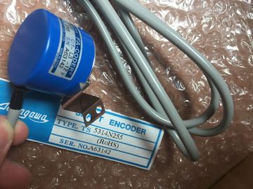
| Brand Name: | Tamagawa |
| Certification: | CE |
| Model Number: | TS2640N71E10 |
| Minimum Order Quantity: | 1pcs |
|---|---|
| Packaging Details: | carton |
| Delivery Time: | in stock |
| Payment Terms: | T/T, Western Union, MoneyGram, MoneyGram |
| Supply Ability: | 100pcs/week |
| TAMAGAWA: | TAMAGAWA | COLOR: | BLACK |
|---|---|---|---|
| Material: | Iron | Temperature: | Iron |
| Wire: | Wire | TS2640N71E10: | TS2640N71E10 |
| Japan: | Japan |
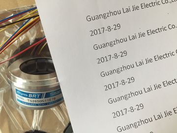
TS2640N71E10
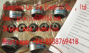
Guang Zhou Lai Jie Electric Co.,LTD
Please contact with “Tommy” for the price
TS5013N60
TS3641N22E7
TS5208N68
TS5210N450
TS4503N1202E200
TS3103N178
TS3664N2E4
TS5013N61
TS3641N2E3
TS5212N351
TS5210N453
TS4503N1205E200
TS3103N255
TS3664N50
TS5016N60
TS3641N12E3
TS5212N510
TS5210N458
TS4503N1828E100
TS3103N302
OAH14BSD
TS3667N1E2
TS5013N63
TS3641N32
TS5213N550
TS5210N530
TS4503N2000E100
TS3103N40
OAS66
TS3667N11E2
TS5016N61
TS3641N38
TS5213N551
TS5210N54
TS4503N2070E100
TS3132N32
OAS66
TS1857N16EP
TS3667N2E5
TS5016N63
TS3643N2
TS5308N510
TS20E12
TS4503N2202E200
TS3134N21
TS3667N2E6
TS5016N64
TS3643N212E5
TS530N33E9
TS2151N121E9
TS4503N2036E501
TS3134N22
OIS1000CT3L5V108
TS3667N3E7
TS5017N60
TS3643N233E8
TS5312-N250
TS2151N141E9
TS4506N1202E200
TS3134N317
OSE10243158
TS3667N3E8
TS5019N60
TS3653N11E2
TS5313N122
TS2228N33E1
TS4507N1002E200
TS3134N52
OSE5K-6-12-108
TS3667N13E8
TS5013N68
TS3653N12E5
TS5320N632
TS2640N141E172
TS4507N1202E200
OSE5KN-6-12-108
TS3674N37
TS5013N69
TS3653N13E8
TS5420
TS2640N181E100
TS4507N1205E200
![]()
![]()
![]()
![]()
| 8 inputs in 4 channel groups ● Measurement type programmab |
Measuring range selection for each channel group |
| Resistor – Temperature |
Configurable diagnostics and diagnostic interrupt |
| Programmable resolution for each channel group (15 bits + sign) | Limit monitoring adjustable for 8 channels |
Hardware interrupt can be set for violation of the limit
● Fast measurement update for 4 channels
● Hardware interrupt can be set for end of scan cycle
● Potential-free from the CPU
● Supports the Configuration in RUN function
The resolution of measured values is independent of the selected integration time.
Diagnostics
You can find the diagnostic messages grouped under the "Group diagnostics" parameter in
the section Diagnostic messages of the analog input modules.
Hardware interrupts
You can set hardware interrupts in STEP 7 for channel groups 0 and 1. However, set a
hardware interrupt only for the first channel of a channel group, that is, either at channel 0, or
at channel 2.
The figures below show the various connection options. These connection examples apply to
all channels (channels 0 to 7).
With a 3-wire connection to the SM 331; AI 8 x RTD, you need to set a jumper between M+
and IC+.
Always ensure that the connected IC and M cables are directly to the resistance
thermometer.
Wiring: 2-wire connection
With a 2-wire connection to the SM 331; AI 8 x RTD, you need to set a jumper between M+
and IC+ as well as M- and IC- .
There is no compensation of the line resistance with a 2-wire connection. The line
resistances are also measured!
Integration/conversion time/resolution (per channel)
• Configurable
• Basic conversion time in ms
• Additional conversion time for resistance measurement in ms
• Additional conversion time for wire break monitoring in ms
• Resolution (including overrange)
• Interference voltage suppression at interference frequency f1 in
Hz
Yes
8 / 25 / 30
25/ 43/ 48*
0
16-bit (including sign)
400 / 60 / 50
Smoothing of the measured values None/Weak/Medium/Strong
Conversion time (per channel) 25/ 43/ 48 ms
Basic execution time of the module (all channels enabled) 50/ 86/ 96 ms
Mode 4-channel mode (hardware filter)
Integration/conversion time/resolution (per channel)
• Configurable
• Basic conversion time in ms
• Additional conversion time for resistance measurement in ms
• Additional conversion time for wire break monitoring in ms
• Resolution (including overrange)
• Interference voltage suppression at interference frequency f1 in
Hz
Yes
3.3****
100*
100**
16-bit (including sign)
400 / 60 / 50
Smoothing of the measured values None/Weak/Medium/Strong
Basic execution time of the module (all channels enabled) 10 ms
Interference suppression, error limits
Interference voltage suppression for f = n x (f1 ± 1 %), (f1 = interference frequency), n = 1, 2, etc